Backgroundinformation:
The nodes of the layer boundary are an important part of the triangulation. Each node of the layer polygons receives the height of the layers directly above it or of the digital terrain model (if youngest layer). In order to calculate an exact fit of a wedging geological layer at its upper and lower edge, all intersections with the triangles of the triangulation of the overlying surfaces along the layer boundary are recognised and also taken into account for the calculation of the layer surfaces. Therefore, it is necessary that you invest sufficient time in the construction of layer boundaries in the case of wedging layers.
After you have constructed the Profile sections, define the lateral spreads as boundary conditions of the geological layers, as long as the constructed layers do not extend beyond the territorial boundaries. In the latter case, it is recommended to define a simple polygon that overlaps the boundaries of the digital terrain model. Otherwise, select Settings in the right-click menu of the geological layer in the object tree of the 2D-View and set a colour under Line colour. Then select Update in the right-click menu of the layer. This will highlight only those parts of all cross-sections in the 2D-view where the updated geological layer is constructed as an outline.
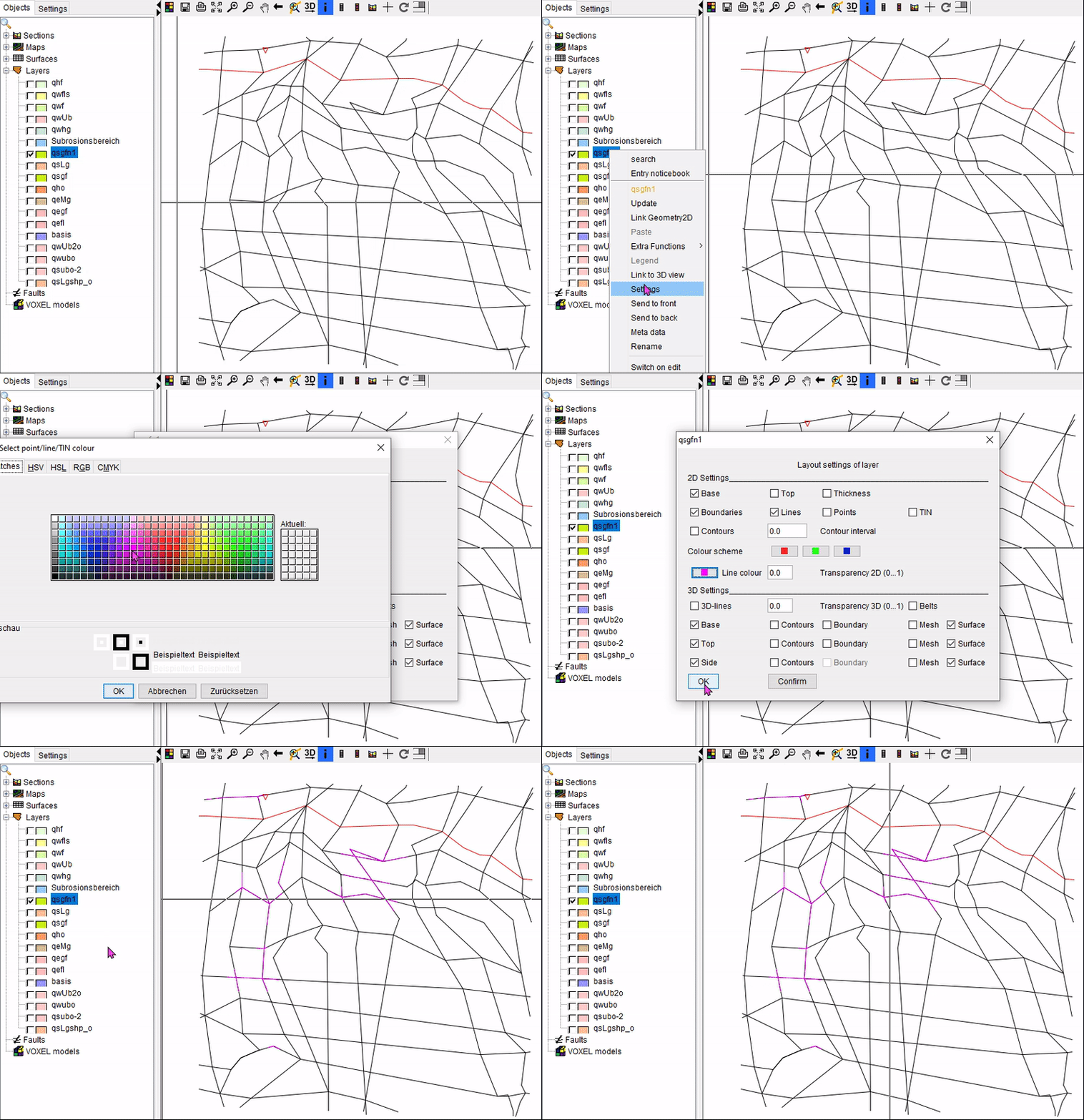
A simple boundary can be constructed that encloses the marked outlines. If you have information about this geological layer from a geological map or other models, mapping, exploration results, the boundaries should be aligned with this information.
You can also copy polygons from loaded polygon shapes and rework them. You can find notes on this under Shapes.
-
Activate the edit mode in the right-click menu of the layer with Switch on edit.
-
This adds the Edit polygons toolbar to the 2D-View toolbar:

-
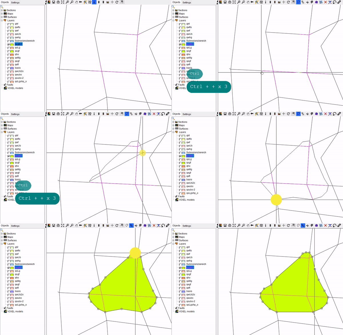
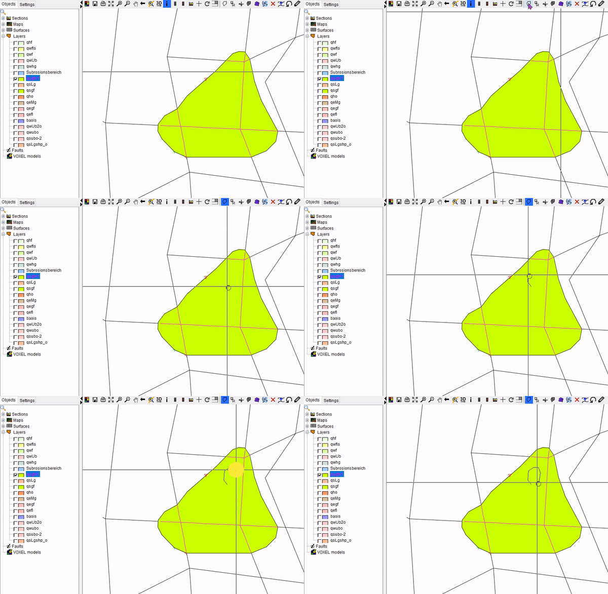
To draw a new layer edging, use the symbol Draw polygon. The edging will be completed with a double click. The snap distance of the Cursor is increased and the line is easier "snaped" to the movement in the profile cuts when Strg + + is used. The edging support points can be adjusted using the symbol. They can be relocated, added and deleted by double-clicking on the line.
-
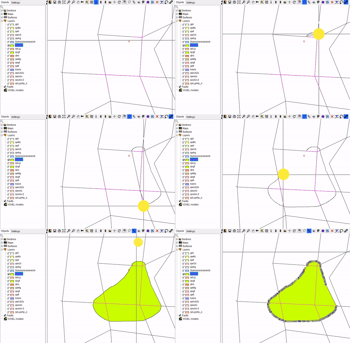
Layer edges can be drawn with the freehand tool
 , which can be combined with Draw polygon
  . As long as the mouse button is pressed, points are generated along the movement of the cursor. The Minimum point distance is used for this:
- With the next two tools polygons can be cut
 and overlapping polygons can be united
  :
:
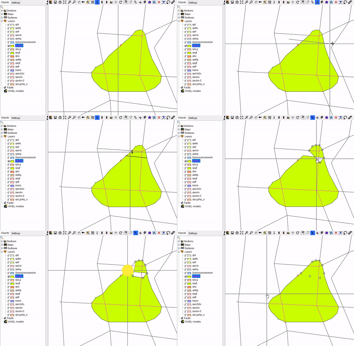
Note: If you have cut polygons, the undo list may no longer work optimally. So you should be sure that you do not want to retrieve several steps before.
-
If you draw a polygon inside a polygon, you create a recess in the layer spread. This can be deleted or closed either by right-clicking with the
 cursor on the inner line with Delete polygon/line or by using the tool Fill islands/holes
  :
:
-
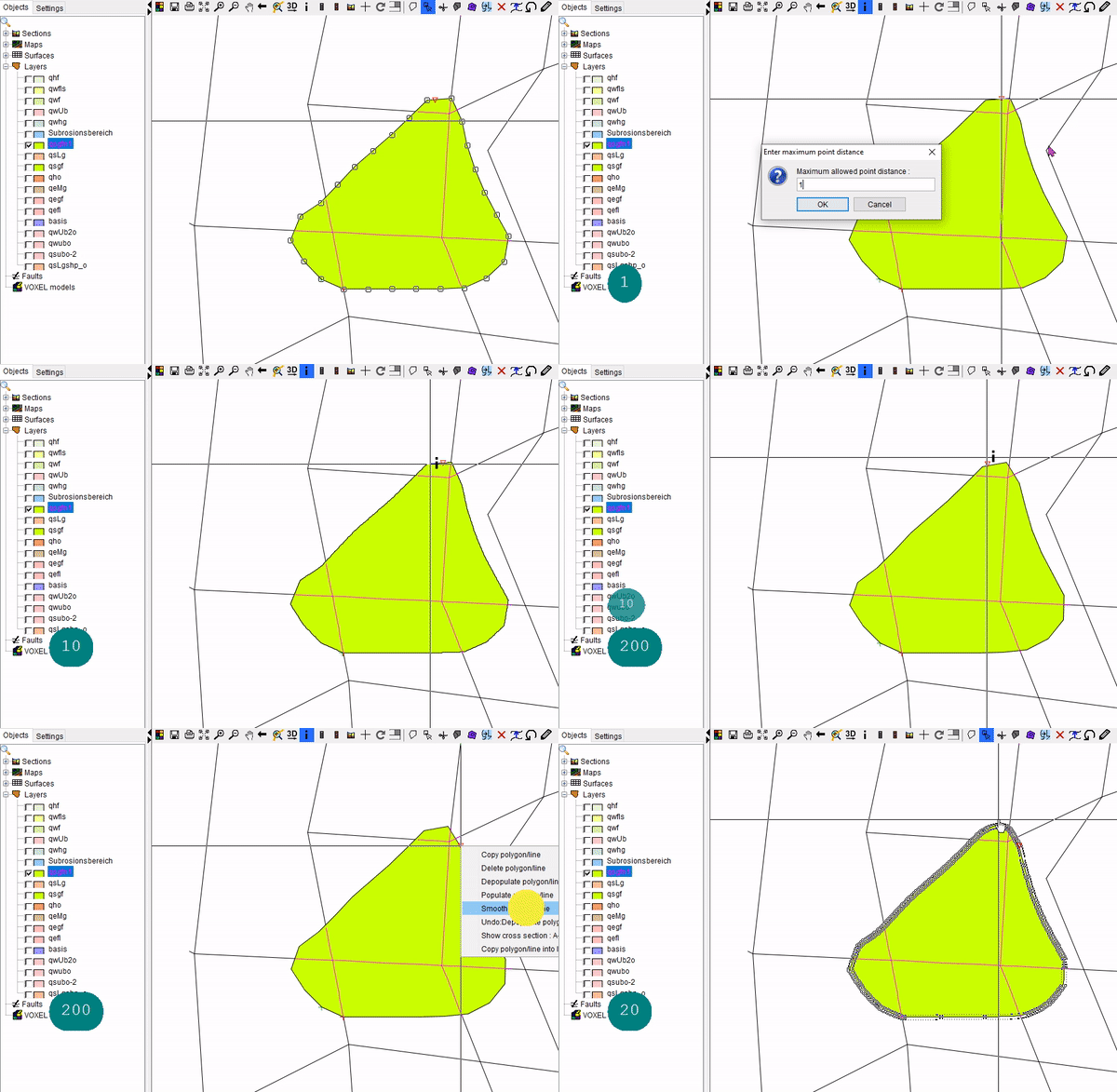
In the right-click menu of a line with the
 cursor you can condense the support points on the line to the entered distances, thin them out or have them smoothed:
-
With the tool Clean polygons
 duplicated supporting points can be removed automatically and the tool Delete polygons
  deletes all polygons of the entire layer!
 -
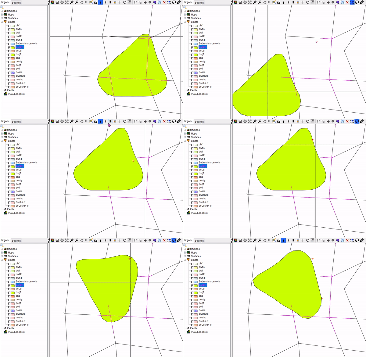
With the two tools on the right, polygons can be moved
 or rotated by means of the mouse wheel
  . For both operations the polygon must be selected with the
  cursor. The processes are ended with a double click:
-
After you have drawn the polygons of the layer, exit the edit mode with a right click on the layer and Switch off edit:
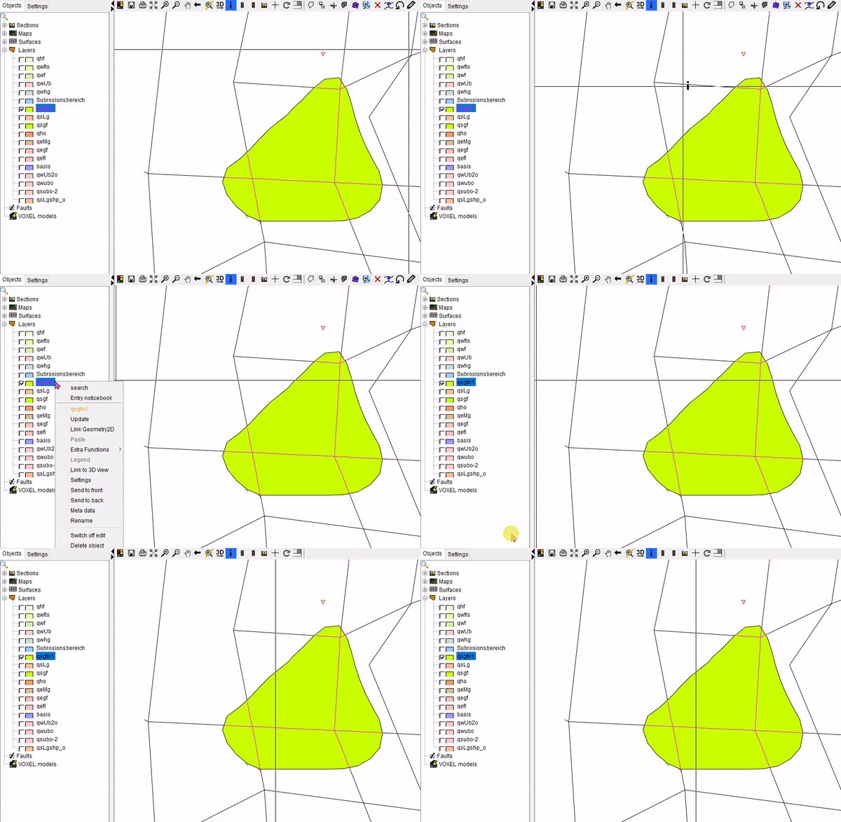
Note: With the right-click menu in the window, you can also undo previously completed steps by using the Undo functionalities. Please note, however, that there is no forward step again.