Background information:
The nodes of the lines created in the profile sections are the essential part of the triangulation. They receive real XY-coordinates and a height during construction, which are derived from the section. A clean construction and a clear naming of the constructed lines is important. The creation of profile section meshes is necessary to have spatially sufficient nodes available for a surface calculation. In addition or as an alternative to profile section meshes, you can also create structure maps for modelling. You can find more information on this here.
The upper and lower surfaces of the constructed geological model units make up the three-dimensional layerformation of digital geological subsoil models. The existing input data as well as the geological distribution in the study area determine the shape and extent of each layer.
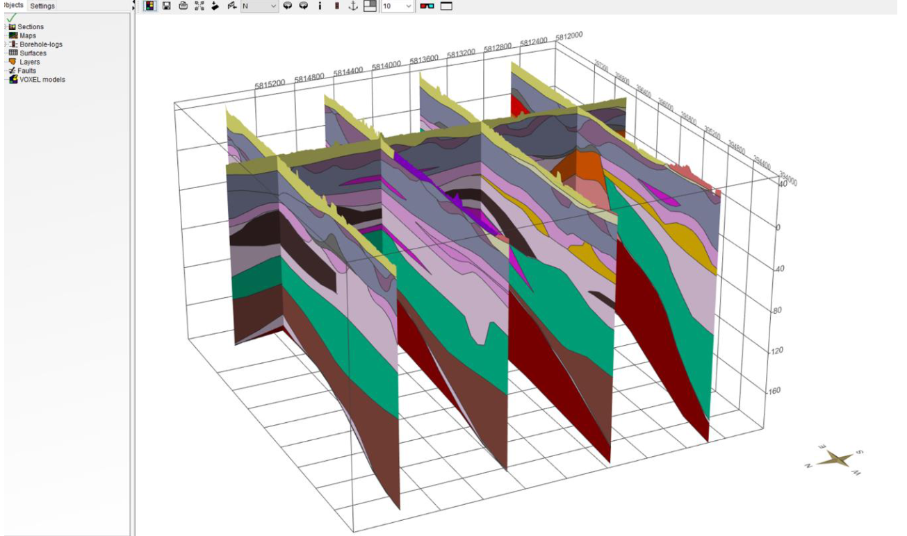
The SubsurfaceViewer allows a correlating of input data in the form of geological profile slices. The software triangulates three-dimensional layer information by creating an extensive net of constructed profilecuts. The procedure for creating profiles will be explained in the following section.
¶ 1. Section establishment
First, add a new section.
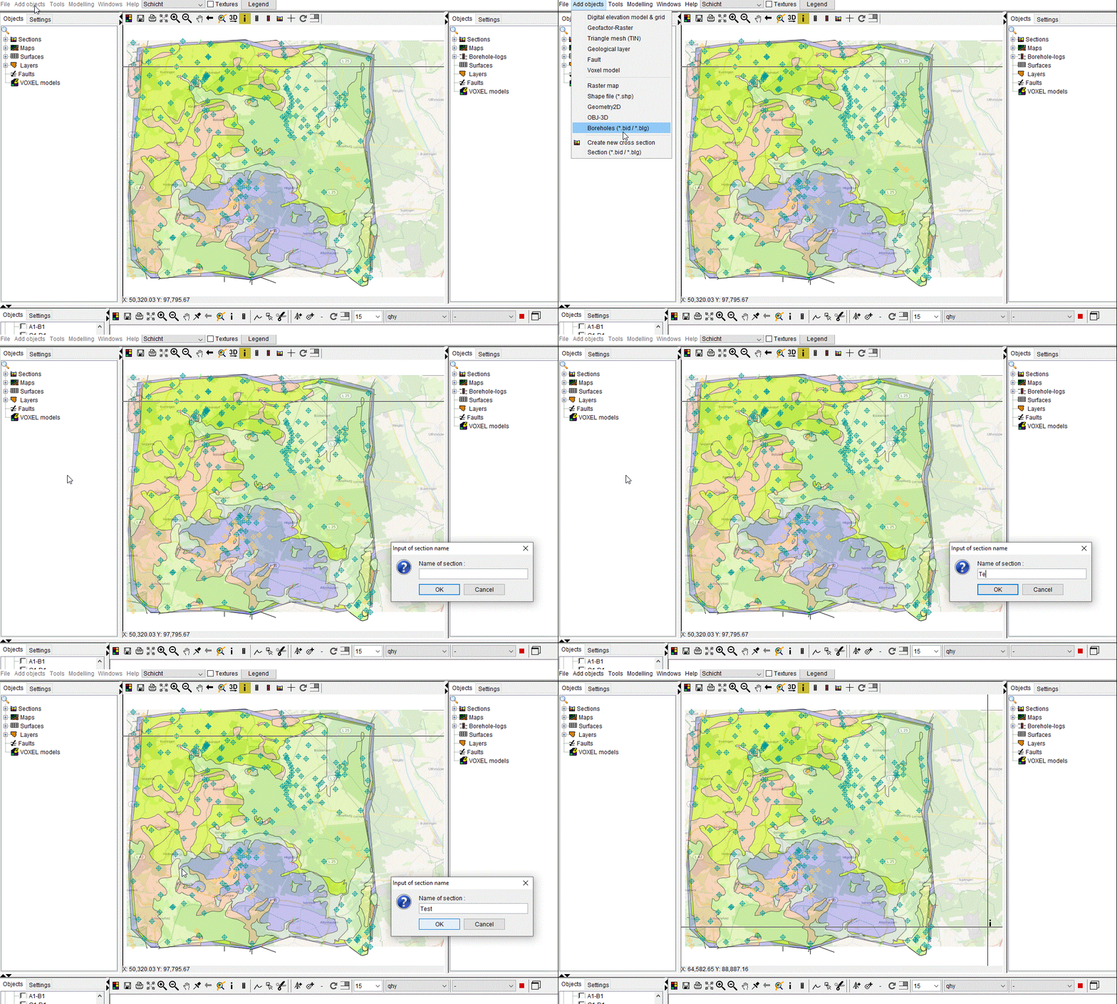
Afterwards, boreholes can be implemented - find

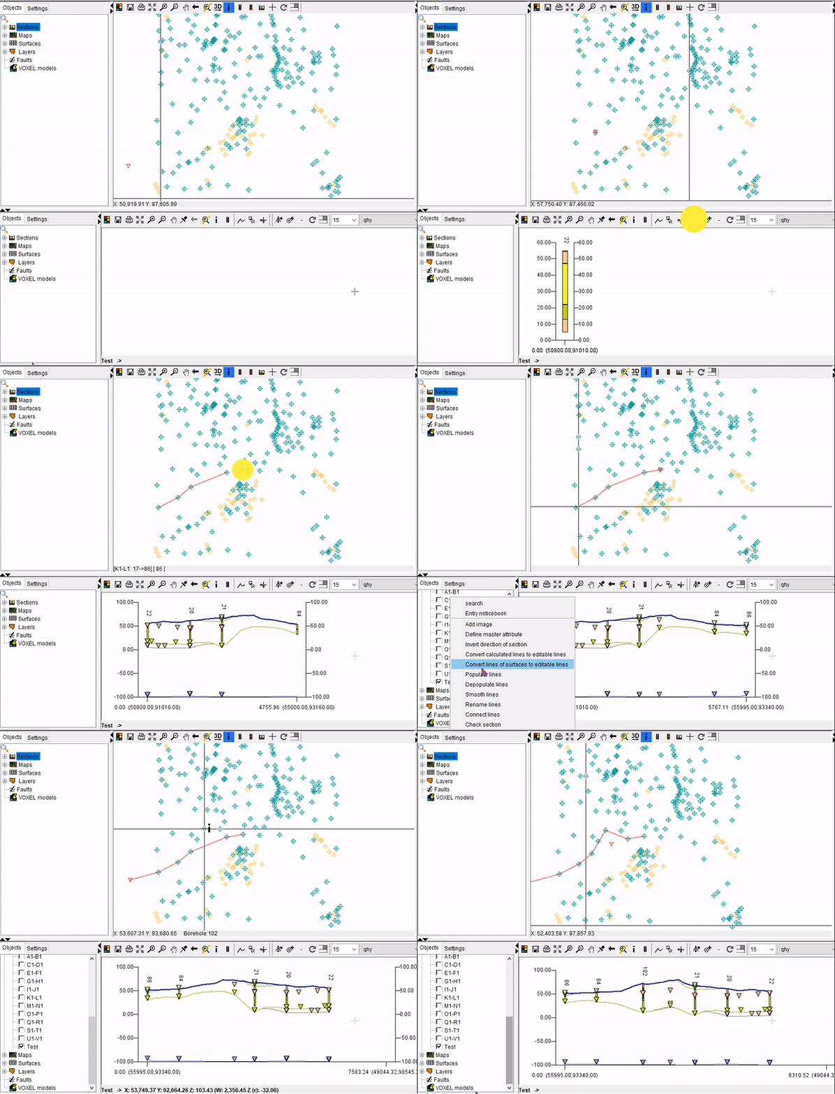
- Add borehole to section - With this tool, selected bore points from the 2D-View are added to the section.
- Add point to section - This tool allows the addition of chosen 2D-view points to the section.
Boreholes are always attached to the right end of the section path. The option to reverse the section's flow direction can be found in the menu of the sections in the file path (Invert direction of section).
Furthermore, boreholes can be inserted within a section. The fact that already-correlated layers are lost throughout this process should be noted. Choose the desired Borepoint, then select Insert Borehole with a right-click on the section.
Alternativly, a list of boreholes (*.bid / *.blg) can be invited, and an automatic section can be created - see here
¶ Crossing Sections
A section network made of intersecting profiles should be created. The intersection points should be on bends which incorporated into both overlapping profiles.It is useful if the intersection points are located on boreholes in order for the respective borehole to be integrated in both intersecting profiles. For geometric detection, it is also helpful if the profile intersection mesh is more or less grid-like and the intersecting profiles are approximately perpendicular to each other.
¶ 3. Correlation between lower layer edges
The modeling of the layers in SubsurfaceViewer always progresses from new to old. Lower edges are calculated, and the upper edge of a layer is determined by the Lower edge of the layer above. It is crucial that the lower edges in the sections be built strictly in accordance with the sequence specified in GVS.
In the drop-down menu you can select a layer - sorted by GVS - and use the tool Draw line . With Edit line
  you can change an existing line: add new support points with a click, move them or remove them with a double click. Each constructed layer bottom edge terminates a layer above it, or extend beyond the end of the profile section. A black triangle on the overlying line marks the outcrop of the lateral layer spread in 2D-View of the line you are currently drawing. You can "snap" the end of the line to these triangles to ensure a clean match between layer bottom edge (in the cross-section view) and layer spread (in the 2D view).
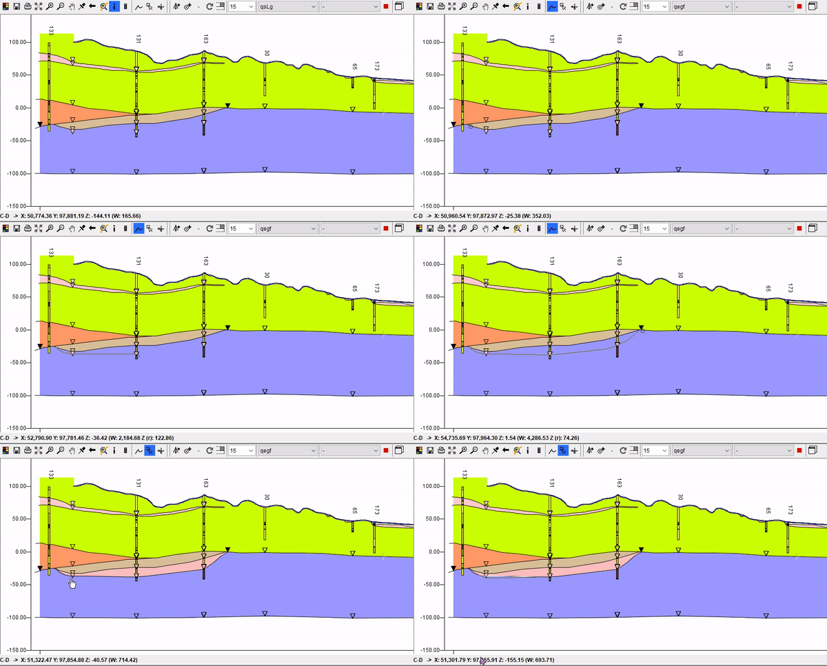
With the Split line tool  a constructed layer bottom edge can be cut. With a right click with the Info tool
  on the line, Connect lines can be selected. This allows line parts to be reconnected at the specified distance:
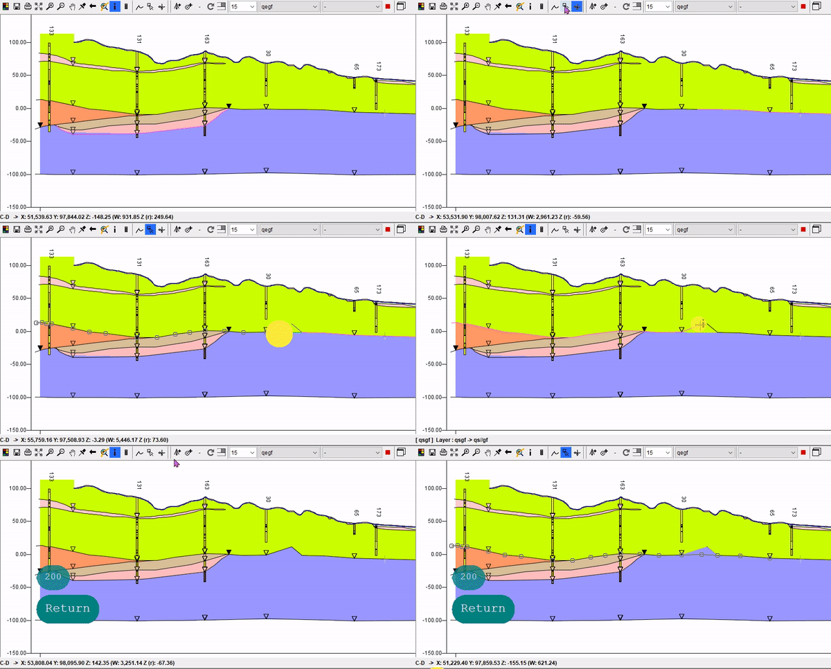
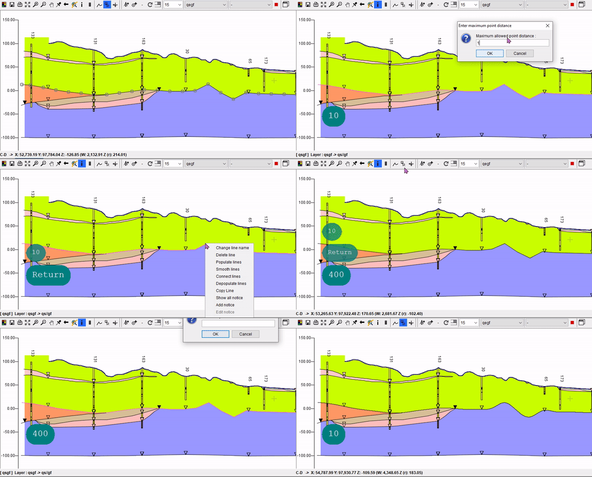
If a line is selected with a right click, options for condensing (Populate lines) and thinning (Depopulate Lines) the supporting points of a line can be selected in the dropdown menu. With Smooth lines lines can be smoothed according to the entered point spacing:
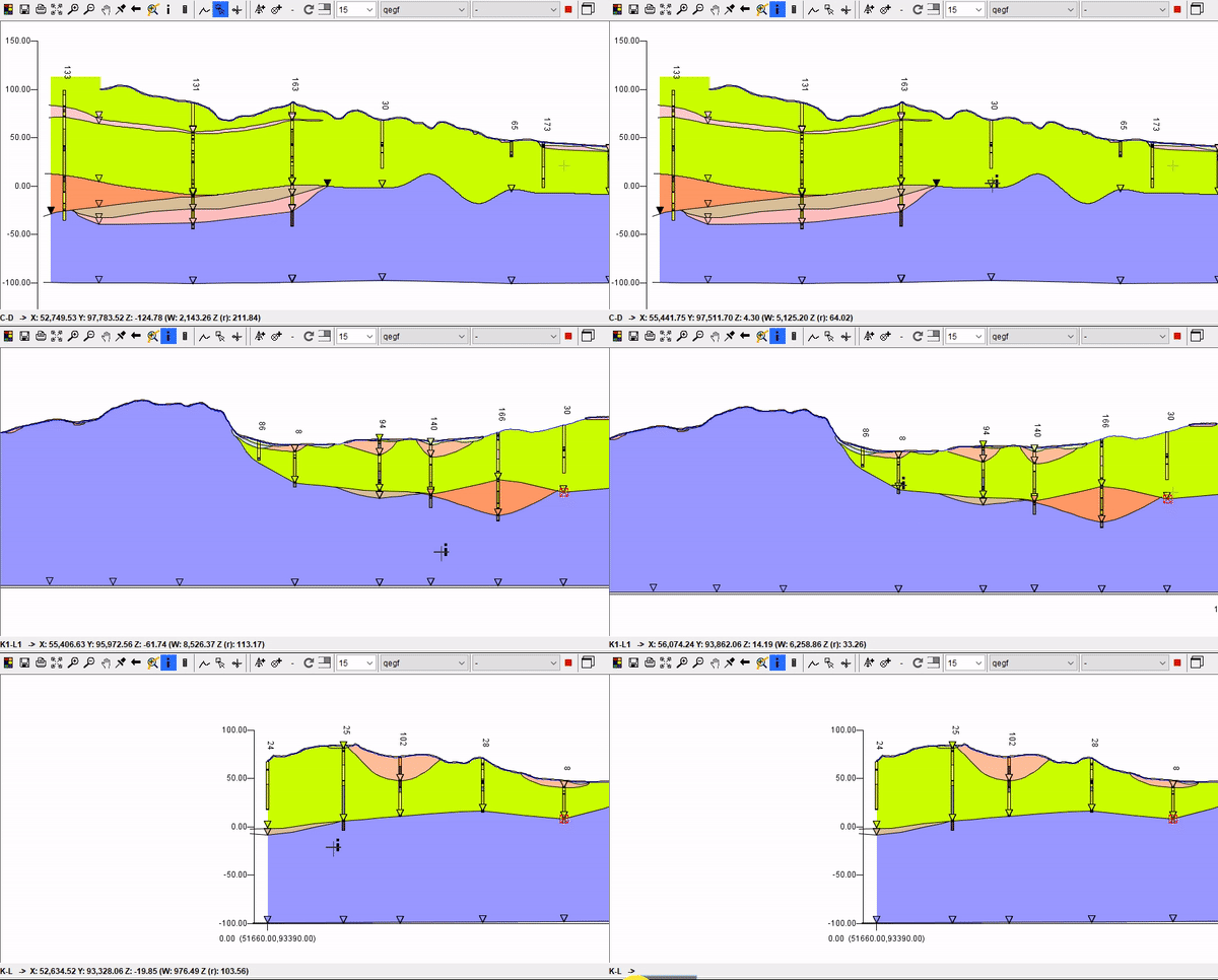
If there are already crossing profile sections with correlated layer bottom edges, these are displayed as crossing points in the form of triangles  in the colour of the crossing layer. You can "snap" the corresponding line to these triangles during construction to ensure an exact match between the profile sections. With a right click → Show crossing section you can jump directly to the crossing profile section. A red cross at the crossing point
  marks the profile you had opened before:
Note: If you have not yet defined a Digital Terrain Model in the Project Settings, no coloured polygons will show above your constructed lines. Also, you should activate appropriate displays in the general Profile Section Settings to see your constructed lines and layer polygons.