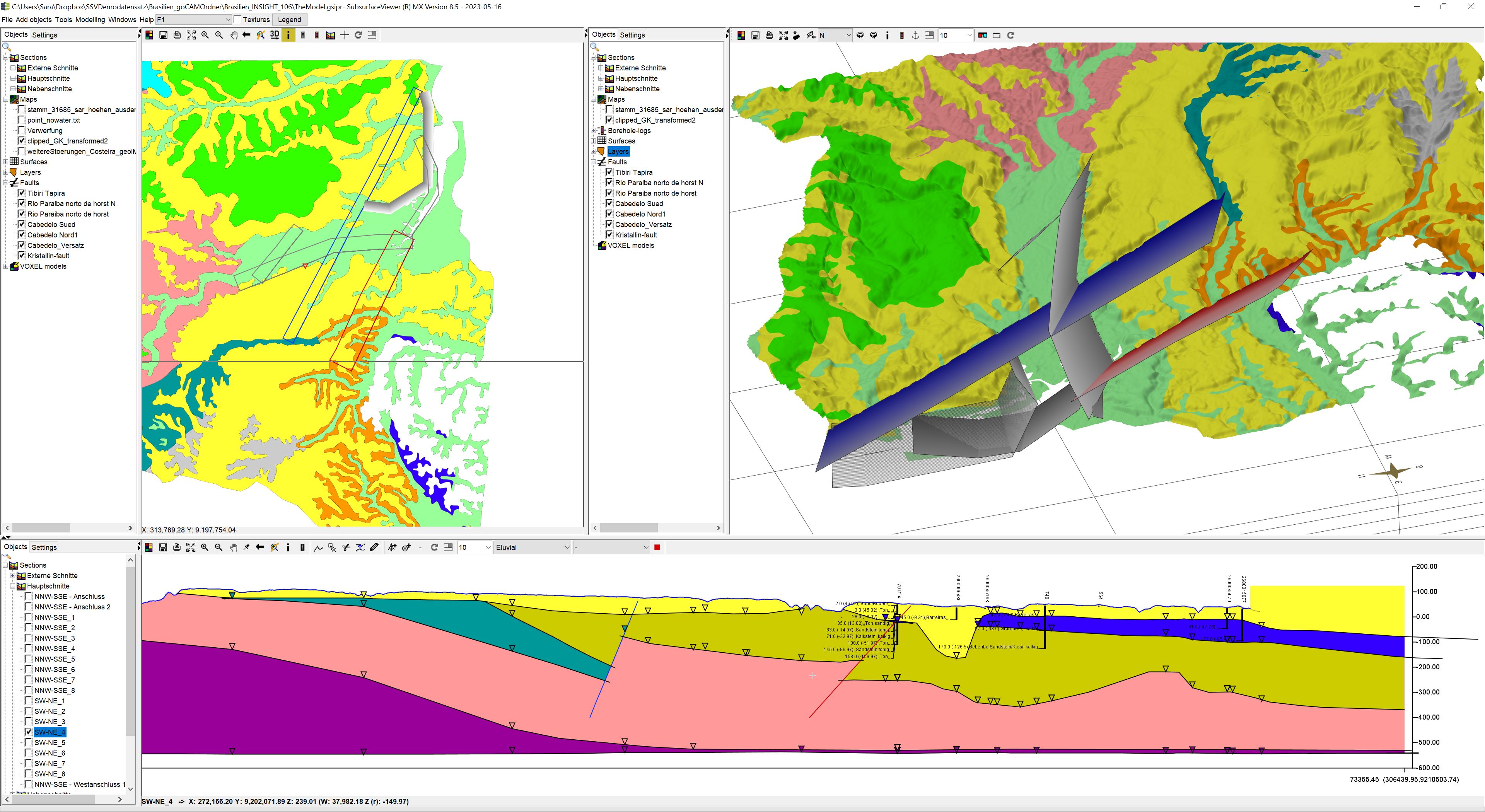
Important note: You can create the surfaces of disturbance systems in the SubsurfaceViewer. You will get back a triangulation in each case. If you create sections manually and with disturbance systems, the resulting layer polygons are adapted to the sections accordingly for visualisation.
**A final layer bottom edge calculation from constructed profile sections in the SubsurfaceViewer does not consider disturbance systems any more. You cannot calculate models with disturbances cleanly with SubsurfaceViewer. You have to resort to other applications for this. Please get in touch with us if you would like to support us to upgrade here.
You load faults in the mainmenubar under Add objects -> Fault.

Note: The model example shown is part of the goCAM research project in preparation for use with FEFLOW.
¶ Create Faults
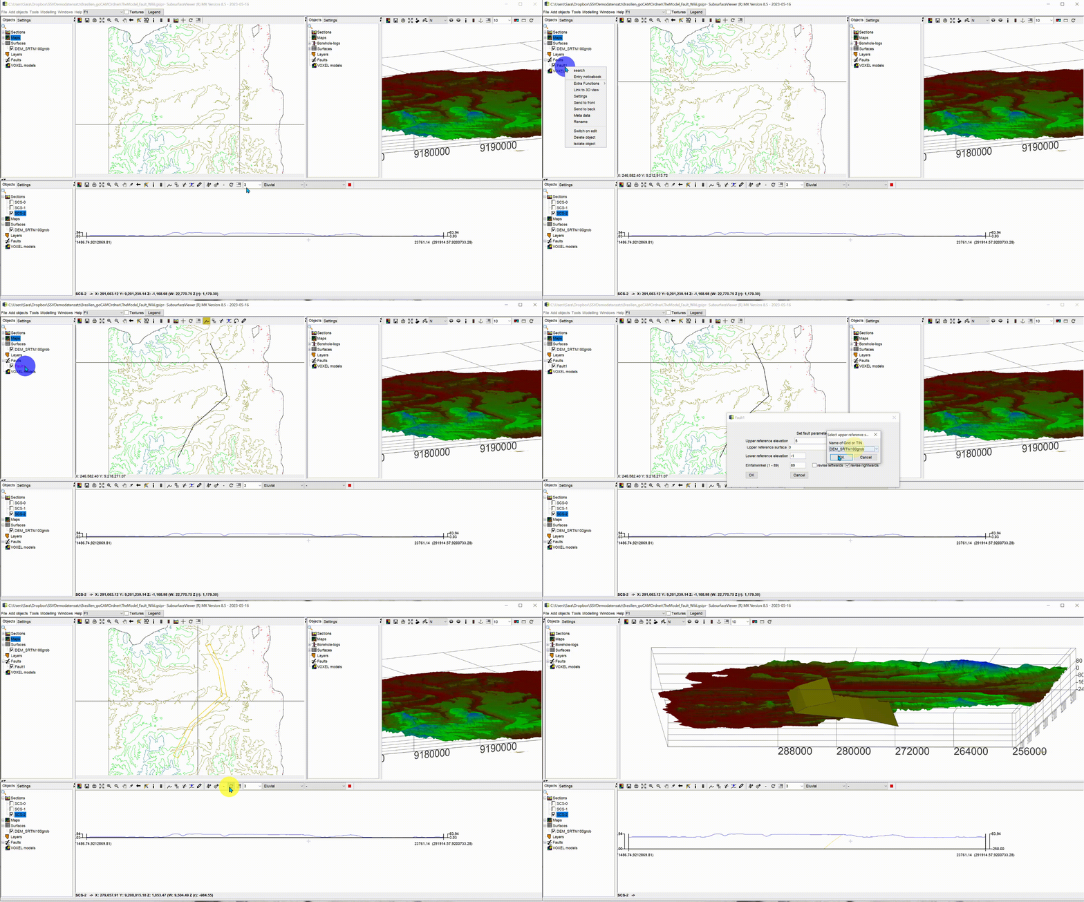
You can create faults with the following workflow:

-
As soon as you call up the function in the menu, a dialogue will open in which you can define the name of the fault. When you confirm, one entry is created in the 2D object tree in the category Faults. Since this object is a triangulation, it is initially empty. No coordinates or other parameters for a calculation have been transferred.
-
Click with a right click on the name in the 2D-object tree and activate the object for editing with Switch on edit in the menu at the bottom. At the top of the toolbar of the 2D window, another toolbar for drawing appears. The explanation of this toolbar can be found here. Draw the line of the fault on the 2D map with the Draw tool. Double-click to complete the line. Then deactivate editing of the object in the same way as you activated it.
-
Open the right-click context menu of the fault and select Extra functions -> Calculate fault. Enter the parameters of the fault in the dialogue that opens. With Upper reference elevation you can determine an absolute height of the upper surface edge. The value is in metres. If you define a surface as Raster or TIN under Upper reference surface, this is preferred as the reference elevation of the upper edge of the disturbance. To do this, use the button -?- and a dialogue opens with a list of the loaded surfaces in the project from which you can select one. If you have set a reference surface by mistake, open the -?- dialogue and press Cancel. The reference surface will be deleted. With Lower reference elevation you set the absolute height (e.g. NN) of the lower edge of the disturbance surface.

The reference heights of the lower and upper edge are set at the set nodes of the drawn fault line in the 2D-View! This means that the denser the line nodes of your fault course are, the more accurate the upper edge of the fault will be, as schown in the picture. You can have the fault course line condensed automatically. To do this, unlock the disturbance object for editing, click on the line with the button and a right click and select Populate line. Enter the target distance of the nodes in the field that opens, e.g. 50 metres, and confirm. In this way, a node is automatically created every 50 metres along the course of the line.
With dip angle you set the angle of incidence of the disturbance from the horizontal. With revise leftwards, revise rightwards you set the direction in which the disturbance falls as seen from the line. Looking north, revise rightwards corresponds to east or south, depending on how the surface runs. If you press revise leftwards, the disturbance will fall to the north or west respectively. -
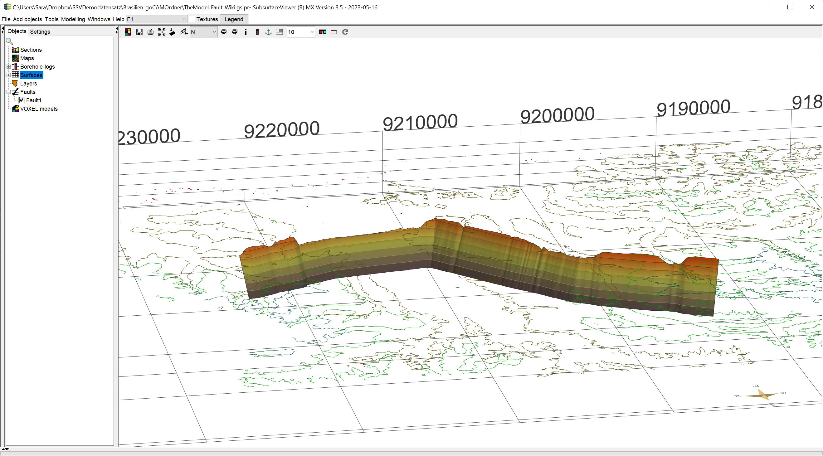
If you confirm with OK, the area is calculated as a triangulation. When the 2D map is updated, you will see the contour lines of the upper and lower edges of the fault. In the updated profile section you see the fault as a line and in the 3D view the area.
¶ Settings
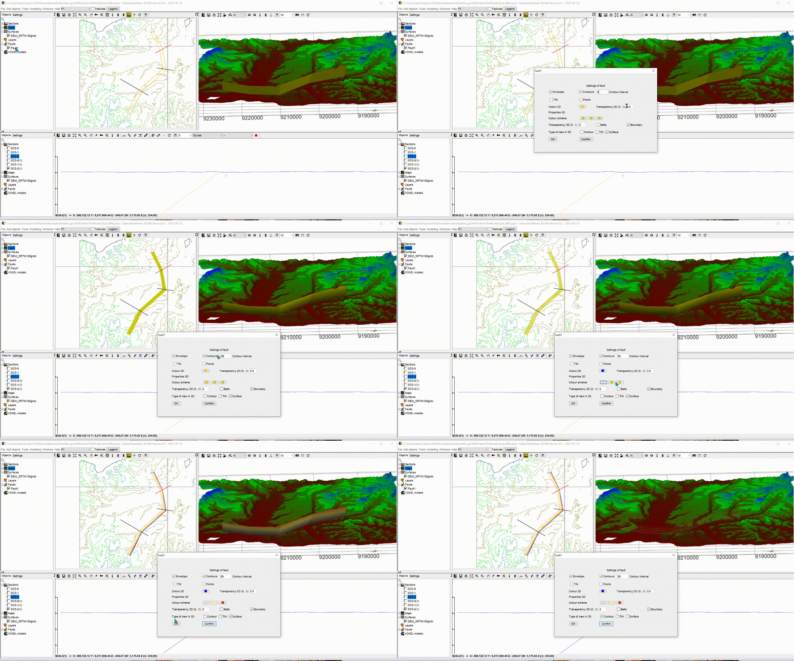
Open the Settings of the disturbance object with the right click context menu in the 2D object tree. There are various setting options for the display of the triangulation. In the upper section of the dialogue box you set the 2D settings and below the settings for the 3D view.

2D:
- Envelope: Shows the contour lines of the upper and lower edge of the fault in the 2D view.
- Contours: Here you activate an isoline calculation of the surface. You have to enter the distance of the contours in metres (Contour interval) in the text field behind.
- TIN: You can display the triangular mesh of the area in the 2D-View.
- Colour2D: Define the colour of the fault line in the 2D-View as well as in the profile section.
3D:
- Colour scheme: Define a colour gradient from the lowest to the highest point of the disturbance using 3 colour entries.
2 Transparency 3D(0...1): Enter a transparency value for the 3D representation of the surface. 0 = opaque, 1 = completely transparent. - Belts: Show the flow surface as bands along every second isoline. You must have calculated isolines for this function.
- Boundary: Show the boundary of the surface in 3D.
- Type of view in 3D: Activate different surface representations.
¶ Functions
In the right-click context menu in the 2D object tree are more options. Most of these functions are general object functions which are explained in [this article].
Note: With Extra functions -> Calculate fault you can recalculate your fault at any time.
With Extra functions -> Load GOCAD Tin you can directly load an externally created flow surface as a GOCAD Tin into an empty fault object. In the same way you can export the surface created under Extra functions -> Export.... You can read about the possible formats [here].