¶ SubsurfaceViewer project formats
¶ GSIPR
The project files of SubsurfaceViewer are XML files with the extension GSIPR. You can view them in a text editor, such as Notepad++. GSIPR files are specially created to SubsurfaceViewer up to version 8.5.
Note that some of the loaded objects are based on their file paths. They need to be accessible when loading a project file. The following object types are affected:
- GVS file
- Legends
- Textures for legends (indirectly via *.bid)
- Raster files
- Voxel files
- Maps in the form of images or shapes
- Shape files
- Tables from the Parameter Manager
- SMCA files
If you have problems loading a GSIPR file, you should check the Info Window for information. If necessary, you can proceed with instructions for repairing a project file.
¶ SVP
You can encapsulate a project file, which accesses files from external paths, with the corresponding objects in a zipped package. The SVP file can thus be transferred back into a folder using a common tool for unzipping. You can also load the file directly into SubsurfaceViewer. Since we assume with this option that the loaded model is a final product, the editing possibilities are limited this way. If you want to give the data package with the model to another modeller, he could unpack this package and load the project file. Read the relevant article under Files in the main menu bar for more information.
¶ Formats for raster files
To load raster files into SubsurfaceViewer, the following formats are recognised.
- ESRI ASCII-grids *.ASC (Description)
- binary grid *.BGF (float precision)
- binary grid *.BGRD
- geoObject grid *.RST
- surfer ASCII Grid *.GRD (description)
¶ Formats for voxel files
To load voxel files into SubsurfaceViewer, the following formats are recognised.
- regular voxel, ASCII *.CSV
- regular voxel, ASCII *.RVMD
- regular voxel, binary *.RVMDH/RVMDB
- irregular voxel, ASCII *.GVMD
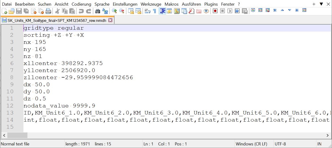
The formats for regular voxels 1., 2. and 3. have a header that looks the same in all cases and is similar to the format of the ESRI ASCII-grid. In 1. and 2. the voxel data are directly written as ASCII beneath this header. In binary format (3.) a second binary file (RVMDB) is written, which contains the voxel data as a float data series (big endian). This means that only numerical data is contained in regular voxels. The 4. header line defines the final data type used in the system when loading. Here you can choose between "int" for integers and "float" for decimal numbers.
Note: If you want to generate a Profiletypemap from a Voxel model, at least one column needs to be defined as a Integer.
If you want to script a voxel model yourself from your external data, you should consider the order of the data series. It corresponds to the sorting +Z+Y+X specified in the header. This means that the data starts with the lowest, leftmost voxel, then the values follow vertically on this voxel in the Z-direction (vertical). These columns are then continued in the Y-direction and this series of columns is appended in the X-direction.
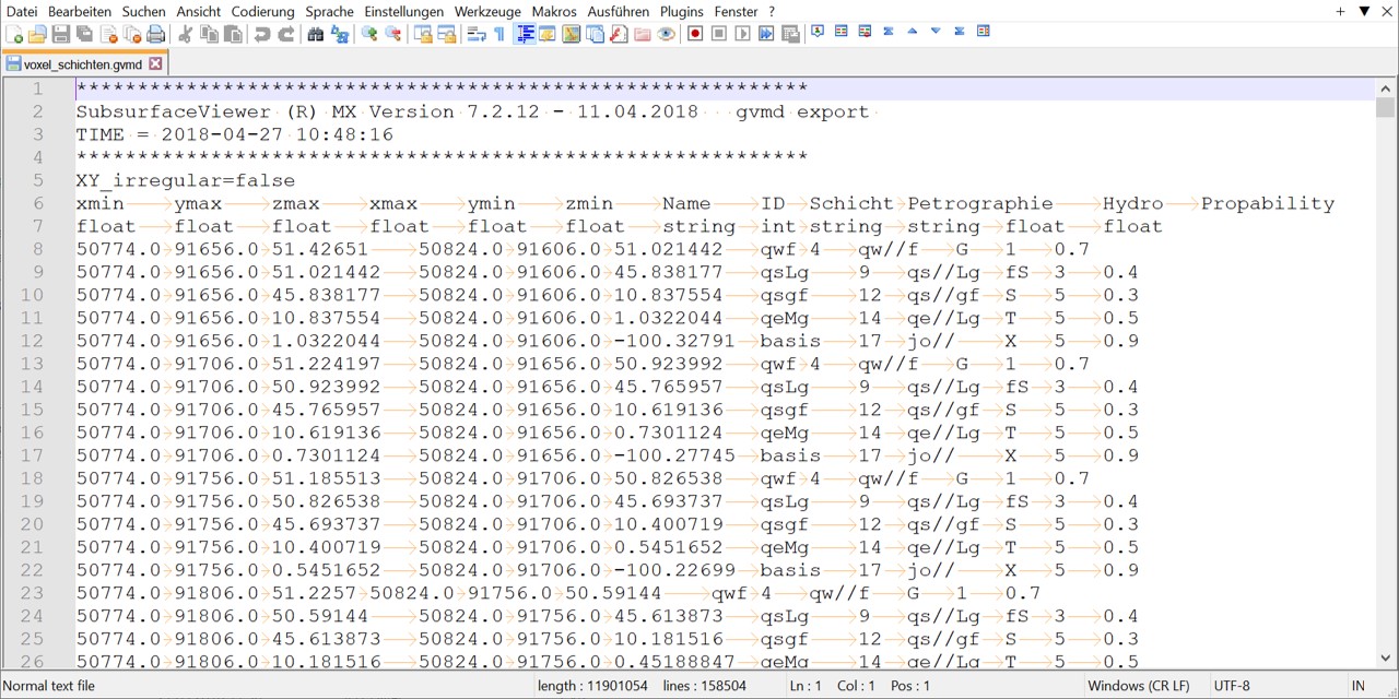
Irregular voxels (GVMD) require a header as shown in the image. The voxel geometries are defined individually with each line and are also processed independently in the SubsurfaceViewer. Here, voxels can represent different geometries and voxel intersections can be used. Furthermore, it is possible to save string parameters and visualise them with SubsurfaceViewer. You use the last header line to determine which data types are included per column. The colums are TAB-seperated.
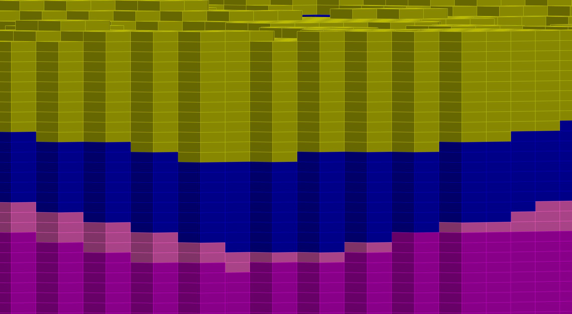
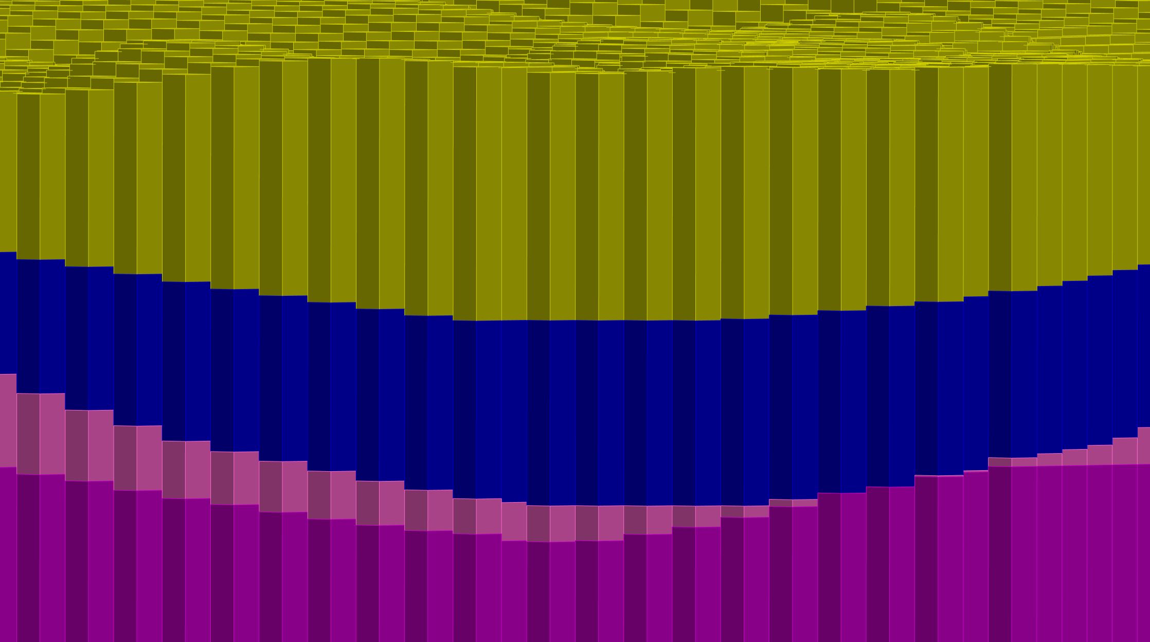
In the regular voxel model, all voxels are the same size. In an irregular voxel model, both the horizontal and vertical extent can be different for each voxel.
regular Voxel irregular Voxel
¶ Formats for triangulations
The easiest way to exchange triangulations with external programs is to use the ASCII GOCAD TSurf triangle file (.ts) format. You can export all triangulations created in SubsurfaceViewer as *.ts files and also import them again.
Further export formats are:
- IFC Tin *.IFC (only suitable for TIN-surfaces and Layer shells)
- OBJ Tin *.OBJ (also import)
- STL Tin *.STL (also import)
- X3D Tin *.XHTML
- WEBGL *.TXT.
- GeoObject Tin *.TIN (only suitable for geol. layers)
Another way to load geological layers into external programmes is to export all nodes of the triangulated surfaces as an XYZ file. This option can be choosed with the right click-menu Export of the layer object.
You can also export and import the triangulation as raster. The suitable formats are found above formats for rasterfiles.
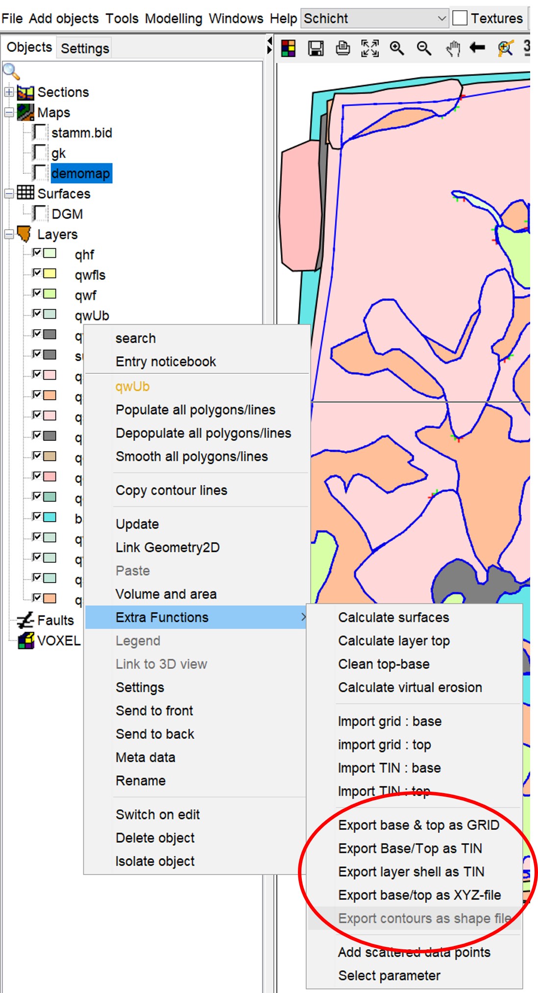
In addition to the import-export formats, you can load point data sets and charge them to a triangulation. You can use the following formats (ASCII tables):
- *.dat and *.bid: These two table types correspond to the format of a typical *.bid table.
- *.ptd and *.xyz: These table types are TAB-separate tables with three columns for X, Y and Z values respectively.
- *.dgm: This table corresponds to the format of an xyz table. You can use rows as seperators.
¶ Forms for Maps
Maps can be implemented as ESRI Shape-files. A description of the forms can be found here:
http://www.esri.com/library/whitepapers/pdfs/shapefile.pdf
Points, lines and polygons are possible. Lines and polygons can be loaded as 2D- or 3D-shapes. Since SubsurfaceViewer works without coordinate system transformations, you need the associated files with the extensions *.shp, *.dbf and *.shx to load shapes. If you export shape files from your SubsurfaceViewer project, these three files are written out.
If you have maps as rasterised images, you need a World file to load them into SubsurfaceViewer. You can create this with relevant GIS applications, e.g. QGIS. Possible image formats are:
- *.jpg
- *.tif
- *.bmp
- *.png
- *.gif
In these two articles you will find descriptions of how to load maps as images: Elevation grid with topographic map und Add objects - Raster map.
¶ Forms for Legends
Legends are ASCII-tables in SubsurfaceViewer. The type of legend and how they are implemented internally in the programme depends essentially on the file extension and the structure. The tables are always without a header and the entries are separated with TAB.
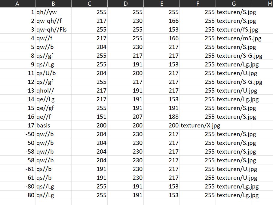
The clour values must be specified in RGBA (Red-Green-Blue-Alpha) in the value range 0-255.
You can use the Legend-Editor to generate SubsurfaceViewer-Legends.
¶ GLEG-Legend
This format is also used in the project settings for the model, you can find more information here. You can import GLEG-Legends for Shape-objects seperately.
¶ NVLEG-Legend
This format is also used in the project settings for the model, you can find more information here.
¶ VOLEG-Legend
This format is mainly used for regular voxel models exported from a layer model. The file should contain the ID of the layers from the GVS-table in the first column. The second column contains a descriptive name. The following columns have the entries RGBA (see above).
¶ BELEG and PALEG-Legend
This format is used for raster data (Geofaktoren and Voxelmodels). If you save with the extension *.paleg or *.beleg, the first column must contain numbers. These define the range of values for which the colours are to be assigned.
For legends of the type *.beleg, the value ranges greater than or equal to the upper entry and less than or equal to the following entry it is displayed uniformly with the colour set above. This is a value classification with a discrete colour assignment.
For legends of the type *.paleg, a colour gradient is interpolated for this value range between the upper and the following colour.
The second column of both legend types contains an alias entry if you want to assign a meaning to the value range.

¶ XMLLEG-Legend
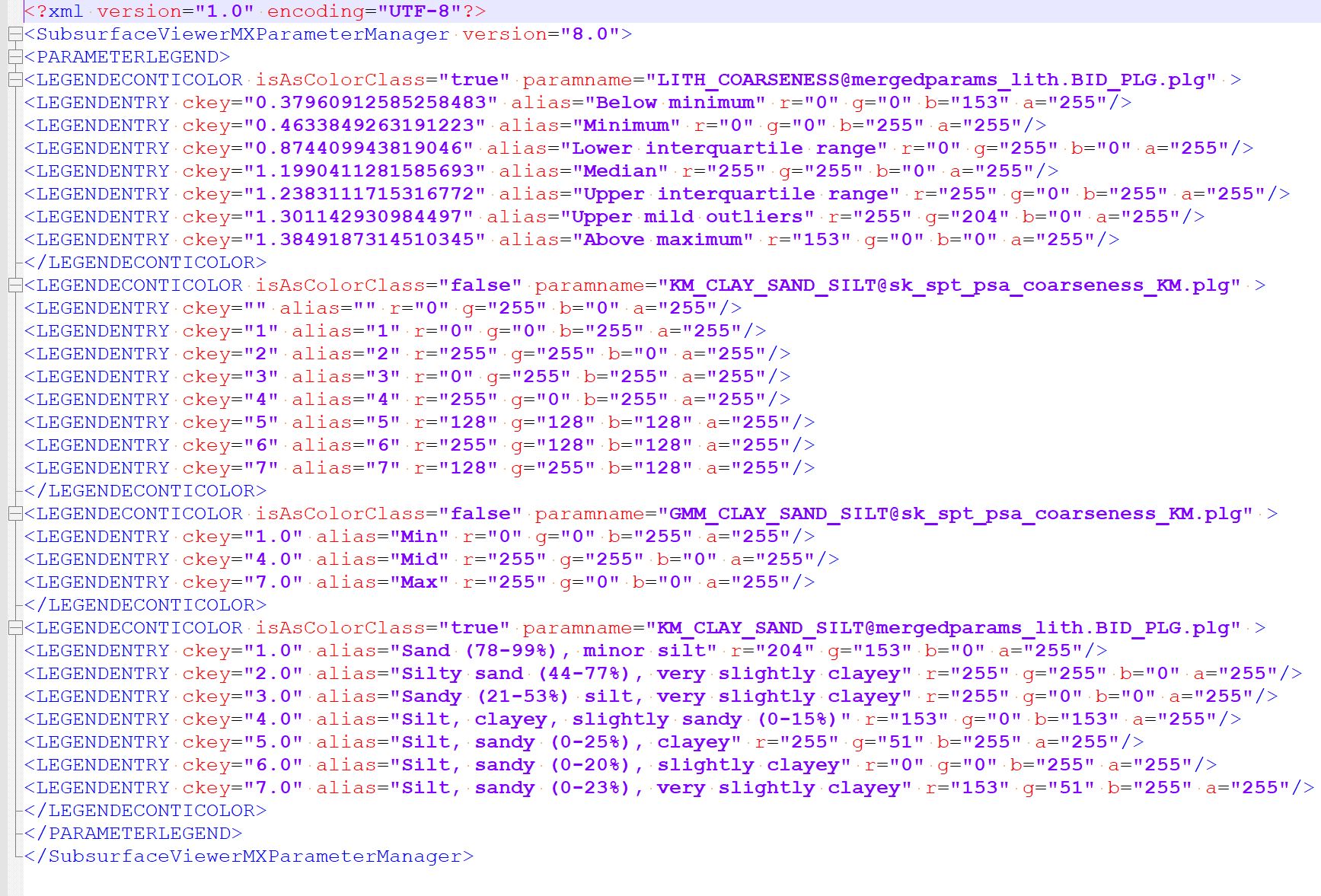
This legend type is to be created especially for integrated Parameters from the Parameter Manager and also to be loaded there. It combines a colouring of several different integrated parameters into one XML file. However, the creation of the individual legends is done in the same way as for those for other legend formats.
¶ Formats for Boreholes
Borehole information is loaded into the system via a combination of master file with extension BID, layer description with extension BLG and measurement data with extension PLG. An EBID table is used to load extended metadata to the master file. In all cases, these are single TAB-separated ASCII tables.
Since layer descriptions for modelling can also be loaded centrally via the project settings, a detailed description of the associated *.blg format can be found here. Numerical data that are only available at certain intervals along a borehole are transferred with the *.plg-Format. They can also be loaded centrally in the project settings. The same applies to the *.ebid-table. It contains further master data, metadata or notes in separate columns to the borehole name.
A *.ebid-file can also be an extended *.bid-file with the same structure, but with more columns.
Note: All related files that load contents to the borehole master data can thus be loaded centrally via the Project settings or to each Borehole point object seperately. Please note, that the centrally loaded contents always have priority. You will notice this if you try to load different BLG contents (i.e. layer descriptions) for a borehole with the same name, i.e. the same key.
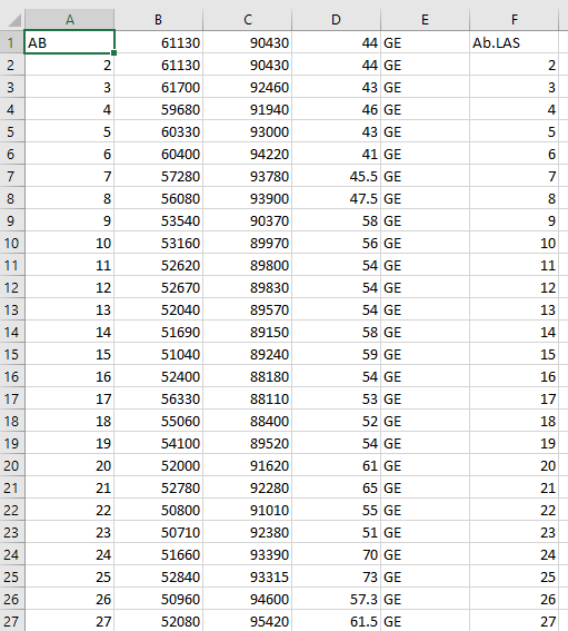
The master data file (*.bid) contains borehole IDs (column A), coordinates (x: column B, y: column C) and the absolute drill approach height in metres (e.g. above NHN) (column D). In column F log data, for example from geophysical borehole measurements, can be added as *.LAS-files by entering the file path. If only the file name is specified, as in the figure on the right, the *.LAS file must be stored in the same folder as the GSIPR-project file.
If you load a *.bid file via the menu Add objects , the order of the columns is not relevant, as you can still configure them for loading. Should you use simplified functions in which synthetic logs at BID positions are exported to a table, such as this or that, the format of the *.bid file should correspond to this one shown here.
Note:
The SubsurfaceViewer needs a point (.) as decimal separator for coordinate or height values, as here in columns B to D, otherwise an error occurs when loading the drilling data.
¶ LAS Files
You can load files in the LAS-format for geophysical borehole measurements to the boreholes. Therefore, you define a column in the *.bid-file, which defines the paths for the respective LAS files belonging to the borehole. The identifier "~A" and the following data are obligatory for reading in SubsurfaceViewer. With certain settings of your boreholes these files are loaded and displayed. Please read the linked articles.
¶ Formats for tables in the Parameter Manager
Note:
The SubsurfaceViewer needs a point (.) for all parameters that are decimals as seperator, otherwise a error will occur in the process.
You can load a normal *.bid-Tabelle in the parameter manager under BID source(s). Here you can use *.bid-structure similar formats. Thus, other separators may be set and the headers may look different. There should be columns for location names, X-coordinate, Y-coordinate and Z-values.
The same applies to loading BLG source-tables,that contain the layer descriptions in a format typical for the SubsurfaceViewer.
If you want to use parser for layer descriptions, it is better to have the file in the *.blg-Format described by us.
The dictionary to be loaded to use the parser for layer description is a simplified XML file with the extension *.alist. You can request a template of this file from us for the English case or a SEP3 translation or download it from our homepage. Details on the file structure can be found in the linked article.
All other files that you load in the Parameter Manager via data source(s) need either an ASCII text table structure, i.e. listed ASCII data with a TAB, space, comma or semicolon separator, or a regular Excel table with a simple format. The arbitrarily structured ASCII tables can have the extension *.dat, *.txt or *.csv.
SubsurfaceViewer usual *.plg-tables or *.itxdat-files aus dem Core Texture Tables are also allowed as file type in the Parameter Manager under Data source(s).
¶ LogExplorer tables
Please read the explanations on grouping and labelling in LogExplorer, to learn more about the usual table formats.
¶ Kerntexturen-Tabellen
Please read the ecplanations for the tool Core Texture Tables, to learn more about the usual table formats.
¶ Formats for Kriging and Inverse Distance Weighting
If you want to use the interpolation functions under the menu item Modelling you can load your input data with the following formats:
Important Note: You must ensure here that the ASCII tables are always seperated with TAB. Furthermore, as mentioned above, it is mandatory to use a dot (.) as decimal separator.
¶ 2D
- *.dat:The format corresponds to the first 4 columns of a *.bid-file, which is explained further above.
- *.bid: You can also directly choose a *.bid-file.
- *.ptd and *.xyz: These files consist of the columns X, Y, Z.
¶ 3D
The 3D data formats are structured in the same way as for 2D, with the exception that they contain an additional column for the value at the XYZ position. Therefore, these files have an additional W in the extension. It follows that the formats look like this:
- *.datw: The format corresponds to the first 4 columns of a *.bid file, which is explained further above and another column behind it for the value at the XYZ position.
- *.ptdw and *.xyzw: These files consist only of the columns X, Y, Z and value.
