Create Geometry2D objects via the Main Menu Bar -> Add objects -> Geometry2D.
.gif)
With a Geometry2D object you can create lines and polygons in SubsurfaceViewer without a Shape or Layer object. It is mainly used in SubsurfaceViewer to create Structure Maps.
Note: You can create both lines and polygons in one object, but it is recommended to create a new Geometry2D object instead of mixing polygons and lines.
¶ Geometry2D erstellen
First create an empty object by entering a name in the window that opens and confirm. The Geometry2D object is displayed in the 2D object tree under the category Maps.
To draw a line or a polygon, unlock it for editing via the right-click context menu with Switch on edit. A toolbar appears above the 2D view.

If you activate the following buttons, you can..:
 ... draw polygons,
 ... draw lines,
 ... edit the nodes of the polygons or lines,
 ... cut polygons or lines,
 ... unite overlapping polygons,
 ... delete islands. (Islands are created when you have drawn a polygon inside another one),
 ... clean up your polygons for duplicate support points.
 ... delete all lines and polygons in the Geometry2D object.
 ... move selected lines or a selected polygon. After selection activate the symbol for moving and move the mouse in the window. This way, the selected objects now move with the mouse. When you found the right position double-click to "release" the lines or polygon at the target position.
 ... rotate selected lines or a selected polygon. After selection activate the symbol for rotating and move the mouse wheel or the arrow keys. This way the selected object rotates. When you have found the right position double-click to "release" the lines or polygon.
 ... draw freehand. Activate either 1. or 2. to tell the system whether you want to draw a line or a polygon. Activate this symbol. If you move around in the 2D-View with the left mouse button pressed, draw as if using a pencil. The saved point distance corresponds to the minimum point distance set in the project settings. By double-clicking you complete the line or polygon.
Note: If you do not want to set the minimum point distance high in your project settings for mutliple use, you should set the lines and polygons drawn with freehand to Clean up nodes.
Note:
You can connect a digital graphics tablet and then draw freehand with it. {.is-info}
¶ Selecting polygons and lines
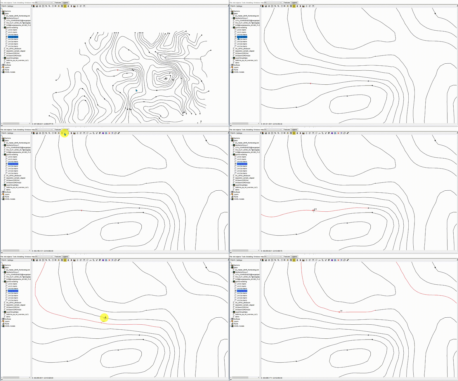
You select lines or polygons using the  button and a left with the mouse on the line or border line of the polygon. For lines, you can make a multiple selection by holding STRG before clicking on the next line. For polygons, you can select only one at a time.
Note: If you select lines in a Geometry2D object that is unlocked for editing, the set name of this line appears above the last mouse position on the right. This helps you when constructing structure maps.
¶ Draw context menu
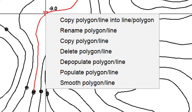
If you have selected the line or polygon with the  button and then use the right click, a context menu opens. Here you can use functions on the currently clicked geometry.

*Copy polygon/line into line/polygon: This converts a line into a polygon or a polygon into a line. In the latter case you will see the conversion if you move the window with the mouse or click the Refresh button at the top of the 2D-View toolbar.
Rename polygon/line: You can rename a line or polygon. This function is basically needed for lines that represent the contents of a Structure Map. Read the linked article.
Copy polygon/line: This copies a selected polygon or selected line(s) into the buffer. You can copy them into another Geometry2D object. You can also copy polygons into a geological layer or use them for a constraint of an IDW or Kriging interpolation.
Delete polygon/line: Delete the selected geometry.
*Depopulate polygon/line*: Use this to thin out the nodes of a line or polygon to a target distance.
Populate polygon/line: With this you condense the node points on a (border) line to a target distance between the nodes.
Smooth polygon/line: This condenses the nodes on an (edge) line to a target distance between the nodes, but a spline function smoothes the line so that it looks more curved.
Important note:
If you have deleted lines/polygons or performed an action on the nodes, an undo function is available in the context menu. With this Undo function you go one step back. If you have cut lines or polygons in between, it is possible that an undo will no longer run. You will receive a warning before cutting. {.is-warning}
¶ General Options

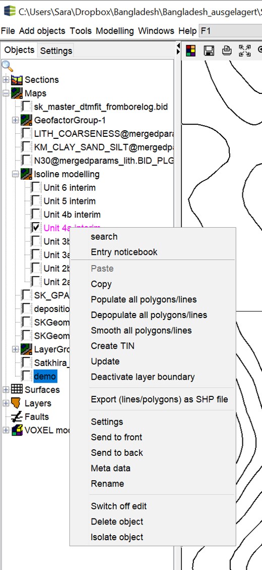
Open the options with a right click in the object tree of the 2D-View. For the general options which are simultaneous for other obkects, read this article.
Paste: This field is only active if one or more polygons or lines exist in the clipboard. You can copy them into here.
Copy: This field copies the entire object into the clipboard.
Populate all polygons/lines: Use this to condense the nodes on all (edge) lines to a target distance between nodes.
Depopulate all polygons/lines: Thins the nodes on all lines or polygons to a target distance.
Smooth all polygon/line: Condenses the nodes on all (edge) lines to a target distance between the nodes, but a spline function smoothes the lines so that they look more curved.
Create TIN: With this you create a triangulated area from the lines that were created in the format of a structure map. You must have named the lines with the height values (absolute heights in metres, e.g. NN). Use the Rename function for it. A window opens where you can make settings for the triangulation. Read the article Triangulations for more information. When creating TINs from isolines, we recommend performing a Refinement, and a Smoothing.
Update: This function is important in the context of Modelling with Structure Maps if you have layer outcrops. It draws the border with the height information of the overlying layer, that you can make a height adjustment of the border of your wedging out layer.
Deactivate layer boundary: This function is important in the context of Modelling with Structure Maps if you have layer breakouts. It deactivates the drawing of the layered outline, see above.
Export (lines/polygons) as SHP file: You can have the constructed lines and polygons written to a shape-file. **The geometries created in a Geometry2D object should only correspond to one type, i.e. either lines or polygons.
¶ Settings

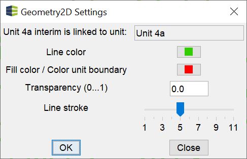
The Settings of the Geometry2D object are explained here. If your Geometry2D object is part of a structural map and has been linked to a geological layer, the top line contains the name of the linked layer for your information.
Below you determine the colours of the lines, the colour of the polygon fill or the colour of the layer outcrop in structural map modelling, the transparency of the polygon fill (0=opaque, 1=completely transparent) and with Line stroke the line thickness of the drawing in the 2D-View.
