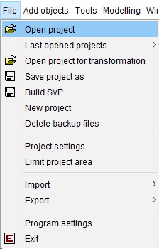
The menu item File contains functions for loading, saving, importing and exporting as well as settings for the software and the currently open project.
¶ Open project
You can open all projects saved on your drive with the SVP or GSIPR format. To do this, click on the menu item File and then on open project. A window opens in which you can see the storage locations of your computer. Open the corresponding folder, select the file and confirm with open.
¶ Last opened project
Under Last opened projects you will find a list of the last opened project files, these can be selected and loaded directly. The lists can be deleted with the option clear List.
¶ Open project for transformation
A projection of the project from GK3 into UTM is possible (with modifications in the procedure also vice versa):
- the transformed project file must contain point-related data (e.g. profiles, TINs, boreholes, layer boundaries, etc.).
- the project is opened via Open project for transformation. A .gkh file with the same name is created in the folder next to the project file.
- this can be used in the external LGLN transformation programme WinGNTRANS_NI to project the contained information into UTM and to create a same-named .utm file. This must be placed in the same folder as the project file.
- The project must be opened via Open project for transformation. The GK3 points are replaced by UTM points in the .utm file.
- The project can be saved in UTM.
To transform from UTM to GK3, the .gkh created in step 2 must be renamed to .utm. This is then used in WinGNTRANS_NI to create a .gkh with GK3 information. It must be renamed to .utm again before step 4.
¶ Save project as
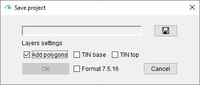
It is possible to save the project. By means of the  tool, the storage location and file name are selected. It is possible to overwrite the current file.
The three boxes below can be used to customise which information should be included in the saved project file:
| Add polygons | → | The polygons of the layer outlines of the layers are saved. |
| TIN base | → | The calculated surfaces of the modelled layers are saved. |
| TIN top | → | The calculated lower edges of the modelled layers are saved. |
If Format 7.5.16 is ticked, the project will be saved in a previous file format to ensure backwards compatibility with SubsurfaceViewer version 7.5.16. This may cause problems with features that did not exist in version 7.5.16 and information may be lost. This function should therefore only be used if absolutely necessary.
¶ Build SVP
With Build SVP, a packed project file in SVP format can be created, containing all relevant information and files (such as BID and GVS). This file can be passed on and opened on other systems on its own.
Before saving, the system asks whether the file should be encrypted:
- If the file is not encrypted, it is to be regarded as a packed archive and can be unpacked with common compression tools.
- If the file is encrypted, it can no longer be unpacked or read by external programmes. It can only be opened by SubsurfaceViewer. It is no longer possible to change or save the content.
If you have loaded geofactors, another pop-up window appears with the list of geofactors. Here you can select those geofactors whose evaluation you want to block by passing on the SVP file to third parties. You should read the article on the SMCA tool.
¶ New project
This function opens a new, empty project file.
Attention!
Any unsaved progress will be lost! The Programme Settings remain as you have set them.
¶ Delete backup files
This makes it possible to delete all the backup files that have been created in order to free up the storage space. If the programme detects that you have a lot of backup files in the designated folder, a pop-up window with the information is displayed.
¶ Project settings
This item is explained in project settings.
¶ Limit project area
The displayed area of an open project can be reduced with Limit project area. By reducing the values on the x- and y-axis, the section is adjusted. This can be done in all 3 windows/views. With Reset the map is displayed in full size. With Cancel the changed values are deleted or confirmed with OK.
¶ Import
Under Import you can import objects from other SubsurfaceViewer project files. This includes:
- cross-sections
- layers
- TINs
- faults
- vertical slices
- horizontal slices
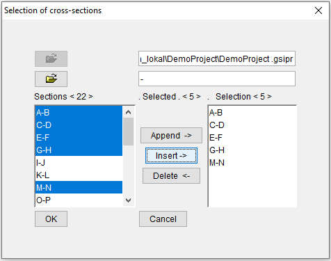
With the open symbol  the project file with the objects to be imported can be opened. When importing cross-sections, there is another
  symbol underneath, which can be used to load an associated .blg file with layer descriptions of the boreholes.
With the Shift or Ctrl key it is possible to select several objects and temporarily attach them to the current project with Append or copy them permanently to this project with Insert.
It is possible to select selected objects in the right-hand list and remove them from the selection with Delete.
The process is confirmed with OK or cancelled with Cancel.
The dialogue looks similar for all import options. In the case of a layer import, you have the option of selecting which geometries you want to import from the layer objects.
In the dialogue for the profile section import you can select whether you want to display profile sections in the selection list that have intersections with a polygon stored in the clipboard. You can specify here with replace during import whether profile sections in the project with the same name are to be replaced with the profile sections that are to be imported.

¶ Export
The submenu Export contains options for exporting data from the structural model to other software products.
¶ Export layers as shape file
The polygons of the geological units (layer) visible in the 2D-View are saved as a shape (ESRI).
If you have only one layer visible in the 2D-View, a multi-polygon is created and the corresponding entries of the columns from the GVS table are transferred to the attribute table of the shape. If you already have calculated layers in the SubsurfaceViewer, you will see the resulting border from the triangulation in blue. This border is decisive for the export.
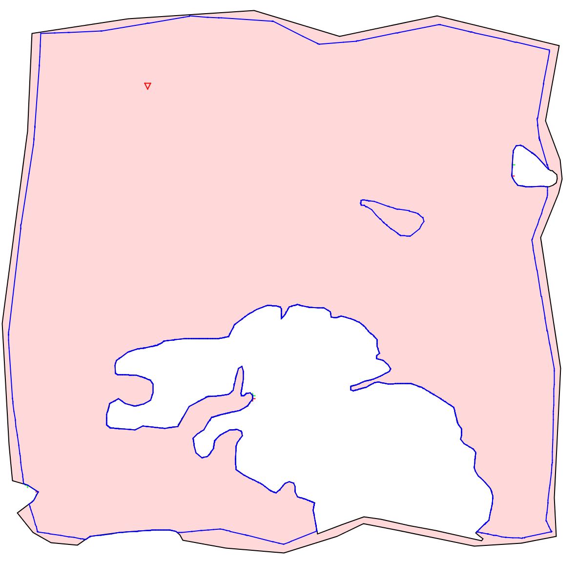
If you have selected several layers and ideally sorted them by GVS (right click of the general layer menu), the visible polygons are clipped to each other. The output is then a set of multi-polygons, each of which also receives the entries from the GVS for the attribute table. The attribute table thus receives one entry per geological unit in SubsurfaceViewer. If you have already calculated the layers, the resulting borders of the triangulations are also decisive for the polygon intersection and the export.
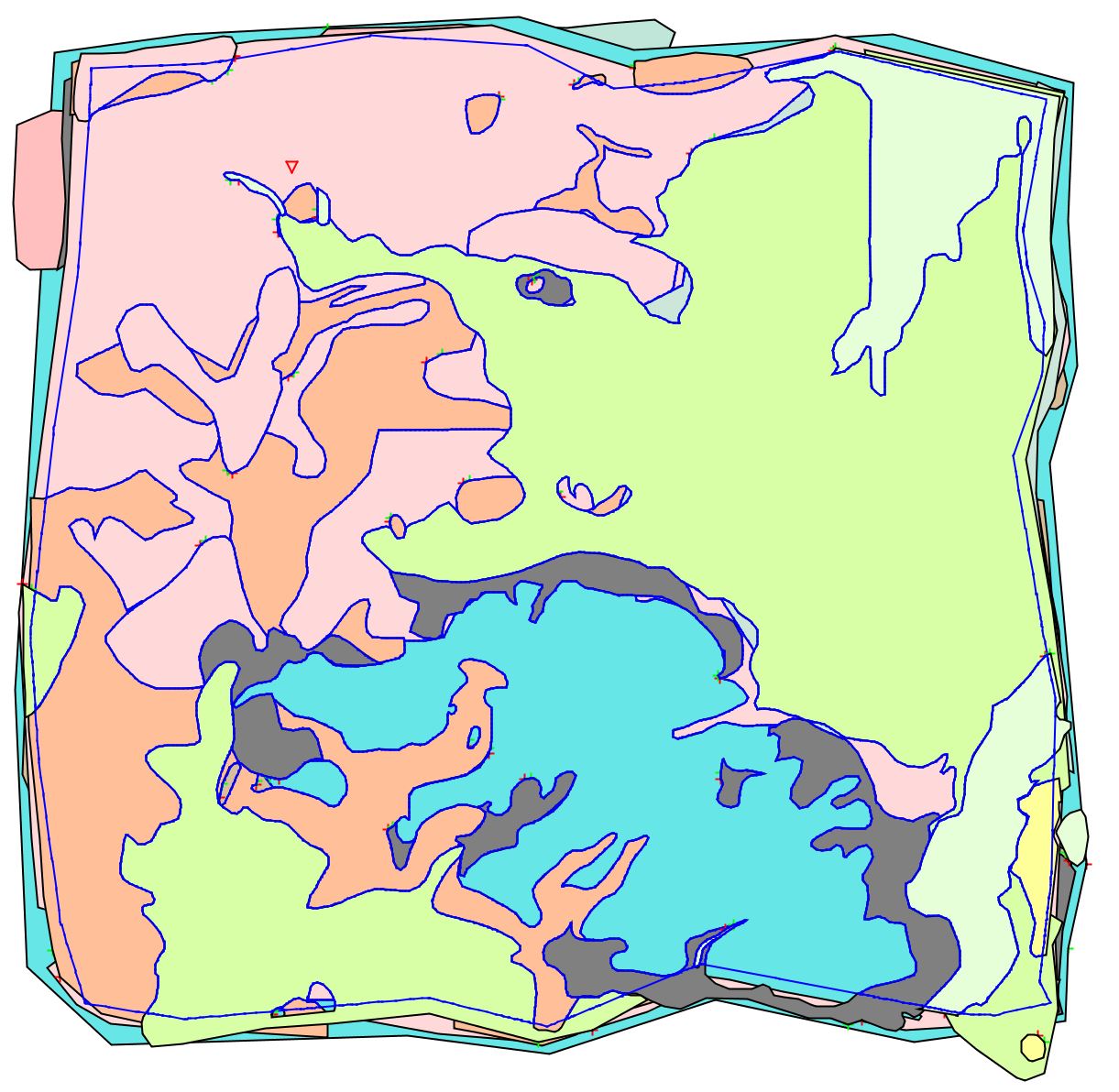
Note: The export of the layer polygons in the correct order and complete therefore corresponds, if everything has been done correctly, to a geological map in shape format.
¶ Export layers as grids
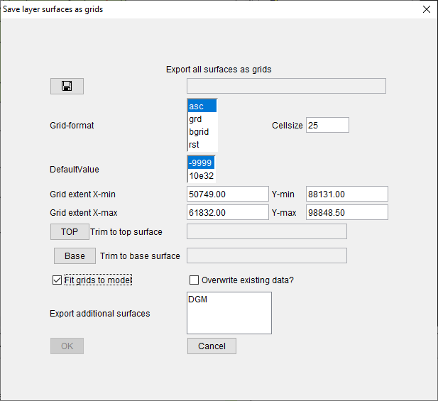
The upper and lower edges as well as the thickness of all layers are saved as grids. The output folder is selected via  . It is possible to select the file format ("Grid-format"), the cell size ("Cellsize"), the total extent ("extent") and the NoData-/Default-Value.
The TOP and Base buttons can be used to select TIN surfaces in the model that will be used as upper and lower boundaries during export.
If, for example, the groundwater surface is selected as the TOP and the Quaternary base surface as the base, only the areas of the layers located between these two surfaces are exported.
A tick in Fit grids to model ensures that the output grid model no longer has any overlaps from subordinate to superimposed layers. With a tick at Overwrite existing data? the overwriting of existing data in the output folder can be activated. With a tick at Fit grids to model the additional surfaces marked in the list can be exported as a grid.
A GSIPR project file is created in the selected output folder, which enables this grid-based model to be loaded in SubsurfaceViewer. Thus, a grid model can also be saved quickly as SVP.
¶ Export layers as project
A project file is saved that contains only the layers.
¶ Export of layers as depth from ground model
This function exports the calculated layers to a new GSIPR project file. However, all height values are converted from metres above sea level to metres below ground level (related to the digital terrain model selected in project settings. The layers can then be exported with these values from the newly created GSIPR project file, e.g. as Grids.
To do this, you need to create a DTM with height 0 for the project area and load it in the project settings. Instructions on how to create reference surfaces as triangulation can be found here.
Note: This function is only possible with triangulated models. The digital terrain model selected in the project settings must also be a triangulated surface. Please note that depending on the model size and the density of the triangulations, the export may take several minutes.
¶ Export layers with new DTM
With this function the calculated layers are exported into a new GSIPR project file. The height values are calculated with a new selected terrain model. All height values of the layer surfaces are written in relative heights, i.e. metres below ground level (related to the digital terrain model selected in project settings. These are offset against the new DTM.
The new DTM should have at least the same extension as the model area. If no new DTM heights are found for certain height values of the model, artefacts will occur at this point. In this case, check the result carefully. The constructed layers are not always plausible with a new terrain model, especially if the new terrain model shows serious differences or does not cover the same area. If you need to rework, you can use the import functions and functionalities of the profile sections or structure maps to assemble a new project.
Note: This function is only possible with triangulated models. The digital terrain model selected in project settings and the new digital terrain model must also be a triangulated surface. Please note that depending on the model size and density of the triangulations, the export may take several minutes.
¶ Export layers to MODFLOW
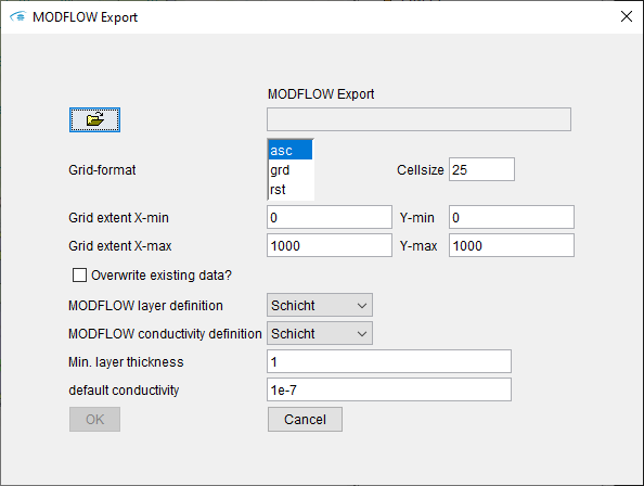
This function exports the bottom edges of the layers as grids. In addition to the known settings for export as grids, there are the following selection options:
- With MODFLOW layer definition a parameter from the GVS file is selected, on the basis of which successive layers with the same value are combined into a layer package. This is done, for example, on the basis of the hydrostratigraphic structure.
- With MODFLOW conductivity definition it is selected from where in the GVS file the information on the permeability coefficient for the layer packages is read out and written into the resulting grids.
- In areas where these combined layer packages do not occur, the minimum thickness specified under Min. layer thickness is assigned.
- The permeability coefficient entered under default conductivity is used if no other information is available.
¶ Export layers as VRML
A VRML file can be created that contains the solids of all layers. The VRML format is used to describe geometries and graphical rendering in 3D browsers. This format is used by 3D printers, among others. It is possible to save in the file format for the ray-tracing software POV.
¶ Export layers as VOXEL
With this option, structural models can be saved or converted as VOXEL models. VOXEL models allow the combination of structural and parameter data. Information about the formats are summarized here. The entries in the dialogue text boxes are in metres.
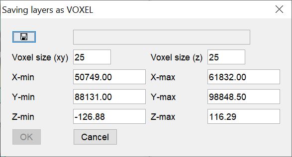
If you export a regular voxel model, the ID of the layer from the GVS table is entered for each voxel. Consider the step size for the vertical resolution (z) of your output, because this is crucial for the information preservation of thin layers.
If you export an irregular voxel model, cuboids will be created that have the horizontal step size (xy) you specified in the text field, but in the vertical direction always map exactly the space between the top and bottom of the layer. Each voxel then has an individual vertical dimension. Thin layers are therefore always mapped in this case. Since text entries are also possible in an irregular voxel model, each voxel receives all entries from the GVS table.
Regular voxel models are used in SubsurfaceViewer for parameter integration (Kriging/IDW). Thus, exporting a layer model as a regular voxel model is an important step if you want to perform layer-internal interpolations, for example.
¶ Export layers at BID positions
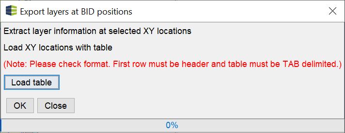
With this simple tool you can load a *.bid-table via Load table, which can be filled with layer information. Here, a synthetic borehole is calculated through the model at each XY position from the *.bid table and the absolute heights of the layer lower and upper edges are entered into the table in each case.
This table can be processed externally or used in the parameter manager of the SubsurfaceViewer to label further field data.
¶ Export of correlation points
The correlation support points from the profile sections of the selected layer are saved as XYZ data in a file format.
¶ Export sections as SHP-File
The courses of the sections in the model are saved as 2D-line shapes.
If you would like to create 3D shapes of the correlated layer bottom edges for your profile sections, read this article.
¶ Export extended claimdata
It is possible to export the extended borehole master data (.ebid) of the current project.
¶ Programm settings
This point is explained under Programme Settings.
¶ Exit
This closes the SubsurfaceViewer.
Note:
Any unsaved progress will be lost! The programme settings remain as you set them.