With Add objects, objects are added to the project. This section lists the objects and data that must be loaded at the start of the project. Information on further functions in *Add objects can be found under Add objects.
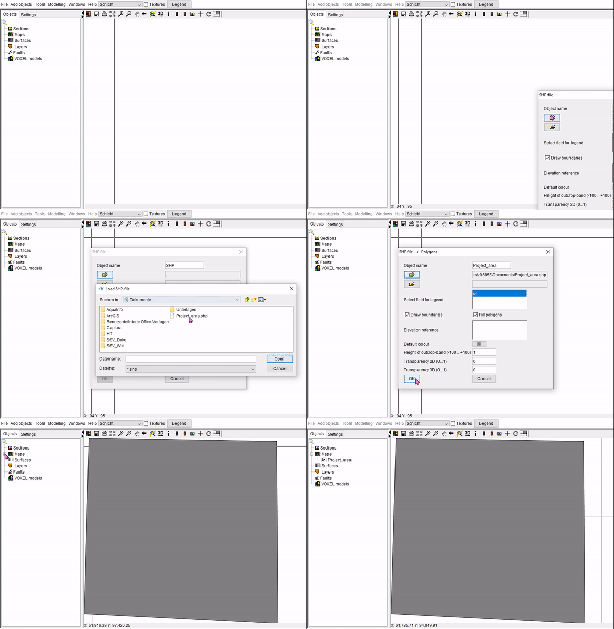
¶ implement project area as shape file
Under Add objects → Shape file (Shapes) you can add a project area's perimeter. It is accessible Maps:
¶ Digital Terrain Model (DTM) as Triangulation
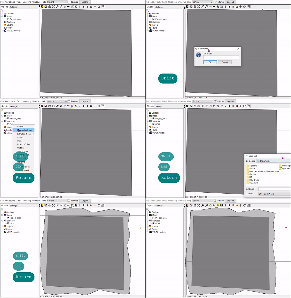
¶ DGM implementation
You may log in using the digital terrain model (DTM) in two steps. You should first add a blank TIN with Add objects -> Triangle mesh (TIN) before adding data to it using the right-click menu in the extra functions section of objects in the 2D-View. An ASCII-format grid is used in the example below:
¶ Tailor DTM to project area
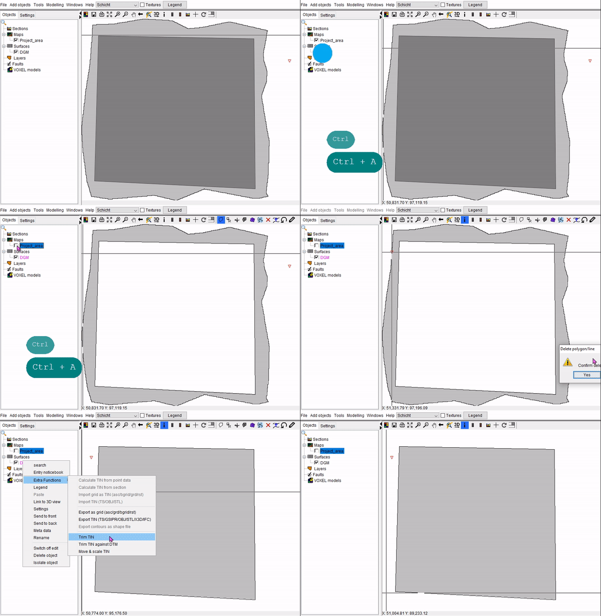
The invited DGM can cut the previously invited project area according to the following schema:
- Open the Shape File's attribute table, which will be used as a template (right-click → Show attribute table).
- Press Strg + a to mark all entries.
- Copy the selection onto the Shape File with right-click → copy.
- Turn the DTM-editing TIN's mode on (right-click → Switch on edit).
- Insert the copied edge (right-click → Paste).
- Remove the outer line with a click and a subsequent right-click with the
 -cursor.
 - When using the DGM-TIN, use the Trim TIN function under the right-click → Extra functions → Trim TIN**Right-click -> Additional Functions menu.
- Complete the DGM-editing TIN's mode by right-click → Switch off edit.
¶ Add boreholes
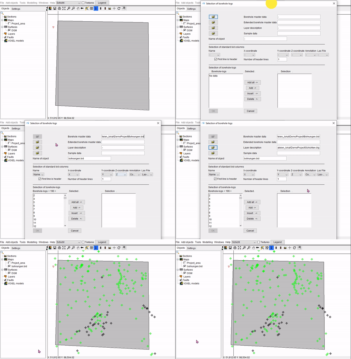
You can add drilling data to the project as master file data and layer data by using Add objects → Boreholes. You can choose which areas to use as X, Y, and Z coordinates as well as which drilling points should be added to the project.
Be mindful of the mandatory format for *.bid-files and *.blg-files as described in the links above. Drillings with inclination, deflection or horizontal drilling cannot be processed at the moment, as this has not been relevant for our project and user group so far. Should you see a need to catch up here, please feel free to write to us.
¶ Add gelological layers
You must add the empty geological layers individually via Add objects -> Geological layer to be able to organize the information from the input data stratigraphic units. They need to be extraced from GVS-file which was implemented in the Projectsettings.
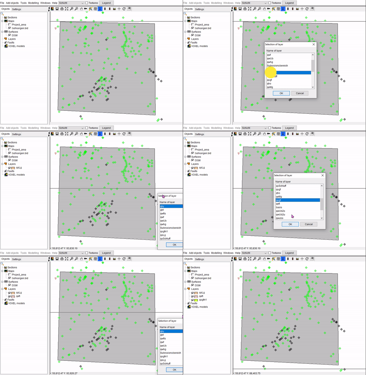
¶ Add topographic maps
Topographic maps from image files (such *.jpg or *.tif, not GeoTiff) can be added via Add object → Raster Map. In the same folder a World file is mandatory. In the Pop-up window you can choose the transparency of the map as well as a height reference. If the DTM is used as the reference point, the relief of the terrain model is displayed on the map in the 3D-view as follows:
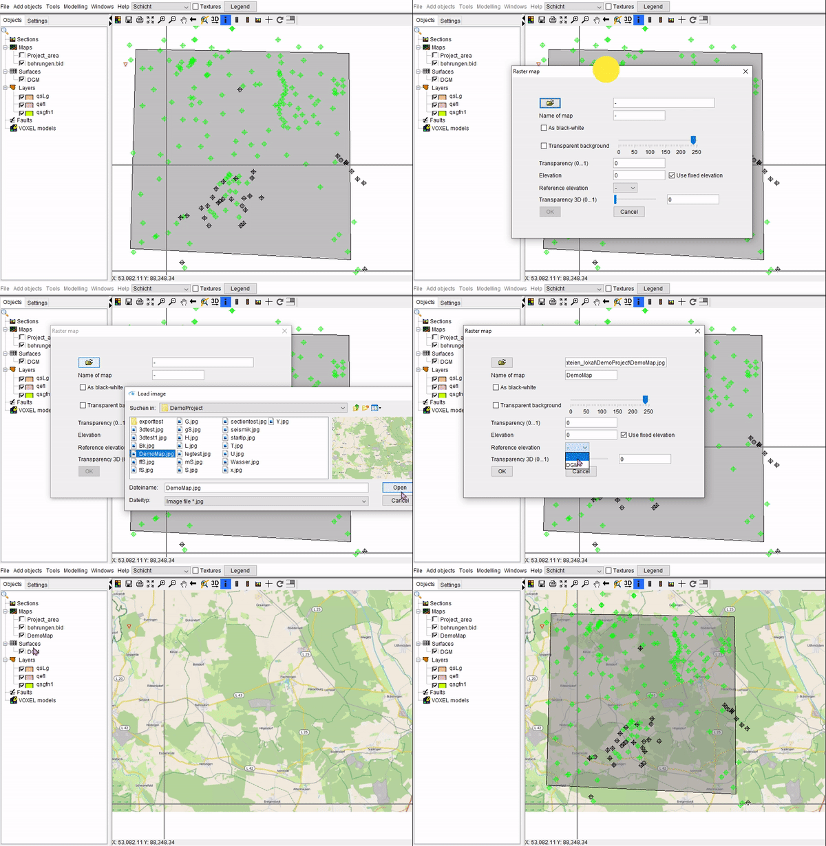
A different example can be found under: height pattern (DTM).
¶ Add a geological map from a shape file
Geological maps can be implemented as Shape (ESRI) Files. The process is similar to that used to import a Project Area from a Shape File. The appropriate layer can be chosen in the window Select field for legend if the geological map has many depth horizons in a single file. A geological map with four layers must be loaded in four separate processes, starting with the oldest. To display the map in the 3D-view the terrain model (DTM)(/en/Funktionen/Hoehenraster) should be chosen as the height reference. Also it is possible to choose different loaded surfaces as height reference for shapes. The geological map's layers are placed on the section during the construction of profile cuts in the 2D Cross Section View. The thickness of these coated tapes can be set in meters in the profile cut under Height of outcrop-band:
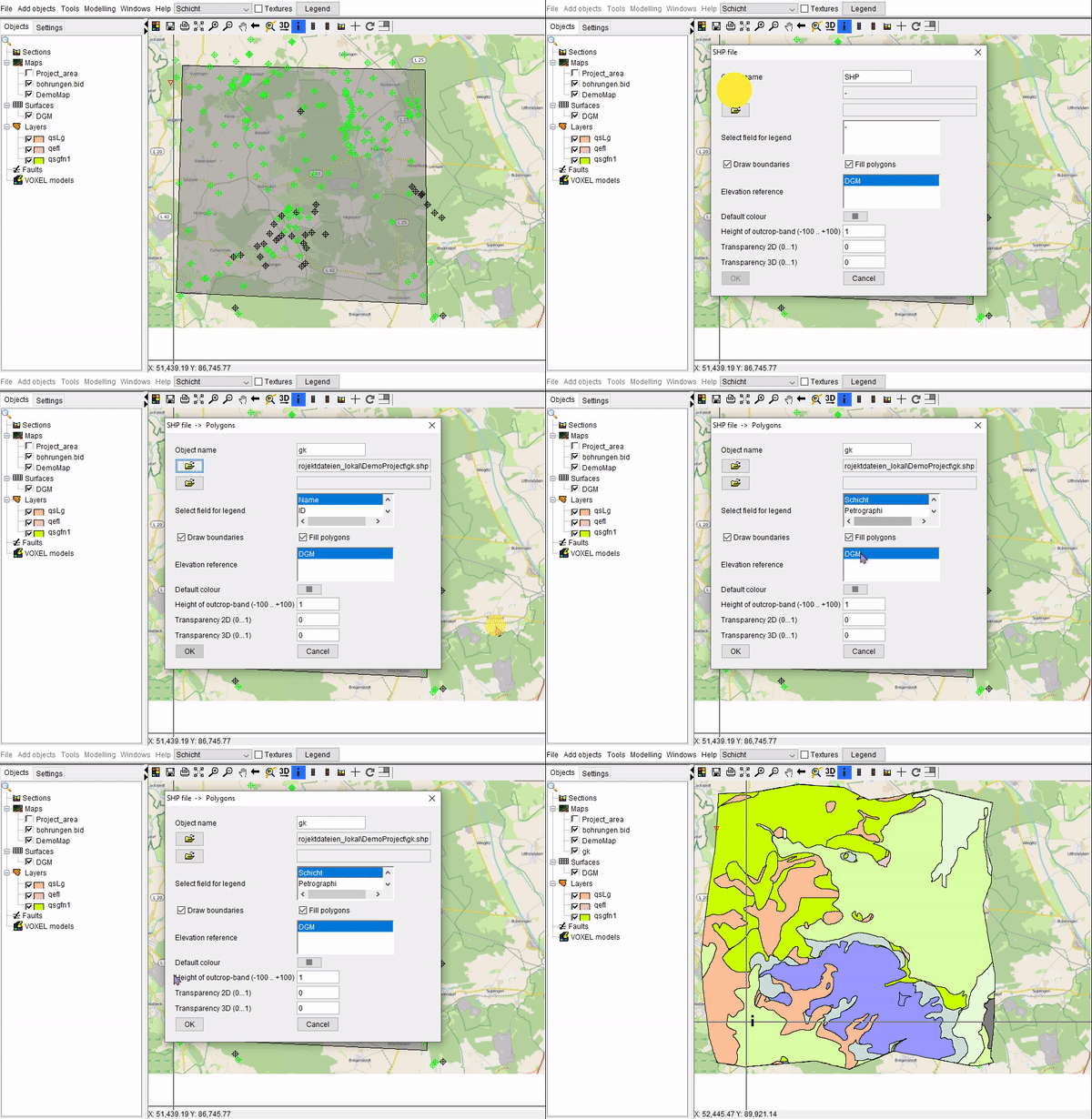
The synchronisation of the crosshairs in the profile section view, the 2D view and optionally the 3D view, makes it easier to match the 3D mapping in the profile sections to the outcrops of the units from the geological map. It is advisable to ensure that the colouring of the geological map matches that of the geological units in the model. To do this, you can either adjust the Project legend or use the legend editor to create a separate legend for the shape. You can also create this with the Legend Editor.